Nissan Qashqai (2007-2010). Manual — part 734

BRC-134
< COMPONENT DIAGNOSIS >
[ESP/TCS/ABS]
C1145 YAW RATE SENSOR
3.
CHECK YAW RATE SENSOR POWER SUPPLY CIRCUIT
1.
Turn ignition switch OFF.
2.
Disconnect yaw rate sensor connector.
3.
Turn ignition switch ON or OFF and check voltage between yaw rate sensor harness connector terminal
and ground.
Is the inspection result normal?
YES
>> GO TO 4.
NO
>> Repair or replace malfunctioning components.
4.
CHECK YAW RATE SENSOR GROUND CIRCUIT
Check continuity between yaw rate sensor harness connector terminal and ground.
Is the inspection result normal?
YES
>> GO TO 5.
NO
>> Repair or replace malfunctioning components.
5.
CHECK YAW RATE SENSOR HARNESS
1.
Disconnect ABS actuator and electric unit (control unit) connector.
2.
Check continuity between yaw rate sensor harness connector terminals and ABS actuator and electric
unit (control unit) harness connector terminals.
Is the inspection result normal?
YES
>> GO TO 6.
NO
>> Repair or replace malfunctioning components.
6.
CHECK DATA MONITOR
1.
Connect the yaw rate sensor connector and ABS actuator and electric unit (control unit) connector.
2.
Select “YAW RATE SEN”, “SIDE G-SENSOR” in “DATA MONITOR” and check yaw rate sensor signal.
Is the inspection result normal?
YES
>> Replace ABS actuator and electric unit (control unit).
NO
>> Replace yaw rate sensor.
Component Inspection
INFOID:0000000000924880
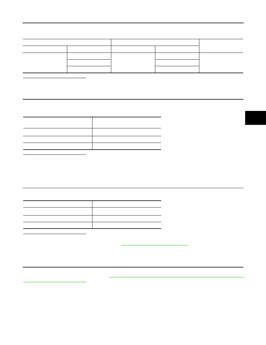
Yaw rate sensor
—
Condition
Voltage
Connector
Terminal
M72
4
Ground
Ignition switch: ON
Battery voltage
Ignition switch: OFF
Approx. 0 V
Yaw rate sensor
—
Continuity
Connector
Terminal
M72
1
Ground
Existed
ABS actuator and electric unit (control unit)
Yaw rate sensor
Continuity
Connector
Terminal
Connector
Terminal
E36
14
M72
2
Existed
25
3
Vehicle condition
YAW RATE SEN
(DATA MONITOR)
Stopped
Approx. 0 d/s
Turning right
Negative value
Turning left
Positive value

C1145 YAW RATE SENSOR
BRC-135
< COMPONENT DIAGNOSIS >
[ESP/TCS/ABS]
C
D
E
G
H
I
J
K
L
M
A
B
BRC
N
O
P
1.
CHECK DATA MONITOR
Select “YAW RATE SEN” in “DATA MONITOR” and check yaw rate sensor signal.
Is the inspection result normal?
YES
>> INSPECTION END
NO
>> Go to diagnosis procedure. Refer to
BRC-133, "Diagnosis Procedure"
.
Special Repair Requirement
INFOID:0000000000924881
1.
ADJUSTMENT OF STEERING ANGLE SENSOR NEUTRAL POSITION
Always perform the neutral position adjustment for the steering angle sensor, when replacing the ABS actua-
tor and electric unit (control unit). Refer to
BRC-78, "ADJUSTMENT OF STEERING ANGLE SENSOR NEU-
>> END
Vehicle condition
YAW RATE SEN (DATA MONITOR)
Stopped
Approx. 0 d/s
Turning right
Negative value
turning left
Positive value

BRC-136
< COMPONENT DIAGNOSIS >
[ESP/TCS/ABS]
C1146 G SENSOR
C1146 G SENSOR
Description
INFOID:0000000000972968
G sensor detects G affecting the vehicle, and transmits the data to the ABS actuator and electric unit (control
unit) as an analog voltage signal.
DTC Logic
INFOID:0000000000972969
DTC DETECTION LOGIC
DTC CONFIRMATION PROCEDURE
1.
CHECK SELF-DIAGNOSIS RESULTS
Check the self-diagnosis results.
Is above displayed on the self-diagnosis display?
YES
>> Proceed to diagnosis procedure. Refer to
BRC-136, "Diagnosis Procedure"
.
NO
>> INSPECTION END
Diagnosis Procedure
INFOID:0000000000972970
CAUTION:
Sudden turns (such as spin turns, acceleration turns), drifting, etc., when VDC function is off (VDC
OFF switch “ON”) may cause G sensor system to indicate a malfunction. However, this is not a mal-
function, if normal operation can be resumed after restarting engine. Then erase memory of self-diag-
nosis.
INSPECTION PROCEDURE
1.
CHECK INSTALLATION STATE OF G SENSOR
Check G sensor is correctly attached to vehicle. Refer to
.
Is the inspection result normal?
YES
>> GO TO 2.
NO
>> Repair or replace malfunctioning parts.
2.
CHECK CONNECTOR
1.
Turn ignition switch OFF.
2.
Disconnect ABS actuator and electric unit (control unit) connector.
3.
Disconnect G sensor connector.
4.
Check terminal for deformation, disconnection, looseness, and so on. If any malfunction is found, repair or
replace terminal.
5.
Reconnect connectors and then perform the self-diagnosis. Refer to
BRC-136, "Diagnosis Procedure"
Is any item indicated on the self-diagnosis display?
YES
>> GO TO 3.
NO
>> Poor connection of connector terminal. Replace or repair connector.
3.
CHECK G SENSOR HARNESS
1.
Turn ignition switch OFF.
2.
Disconnect G sensor connector and ABS actuator and electric unit (control unit) connector.
DTC
Display item
Malfunction detected condition
Possible cause
C1146
SIDE G-SEN CIRCUIT
Side G sensor is malfunctioning, or circuit of side G sen-
sor is open or shorted.
• Harness or connector
• ABS actuator and electric unit
(control unit)
• G sensor
Self-diagnosis results
SIDE G-SEN CIRCUIT
C1146 G SENSOR
BRC-137
< COMPONENT DIAGNOSIS >
[ESP/TCS/ABS]
C
D
E
G
H
I
J
K
L
M
A
B
BRC
N
O
P
3.
Check continuity between G sensor harness connector terminals and ABS actuator and electric unit (con-
trol unit) harness connector terminals.
Is the inspection result normal?
YES
>> GO TO 4.
NO
>> Repair or replace malfunctioning components.
4.
CHECK DATA MONITOR
1.
Connect the G sensor connector and ABS actuator and electric unit (control unit) connector.
2.
Select “SIDE G-SENSOR” in “DATA MONITOR” and check G sensor signal.
Is the inspection result normal?
YES
>> Replace ABS actuator and electric unit (control unit).
NO
>> Replace G sensor.
Component Inspection
INFOID:0000000000972971
1.
CHECK DATA MONITOR
Select “SIDE G-SENSOR” in “DATA MONITOR” and check G sensor signal.
Is the inspection result normal?
YES
>> INSPECTION END
NO
>> Go to diagnosis procedure. Refer to
BRC-136, "Diagnosis Procedure"
.
Special Repair Requirement
INFOID:0000000000972972
1.
ADJUSTMENT OF STEERING ANGLE SENSOR NEUTRAL POSITION
Always perform the neutral position adjustment for the steering angle sensor, when replacing the ABS actua-
tor and electric unit (control unit). Refer to
BRC-78, "ADJUSTMENT OF STEERING ANGLE SENSOR NEU-
>> END
ABS actuator and electric unit (control unit)
G sensor
Continuity
Connector
Terminal
Connector
Terminal
E36
14
M71
1
Existed
21
2
24
3
Vehicle condition
SIDE G-SENOR
(DATA MONITOR)
Stopped
Approx. 0 m/s
2
Turning right
Negative value
Turning left
Positive value
Vehicle condition
SIDE G-SENSOR (DATA MONITOR)
Stopped
Approx. 0 m/s
2
Turning right
Negative value
Turning left
Positive value
Нет комментариевНе стесняйтесь поделиться с нами вашим ценным мнением.
Текст