Nissan Qashqai (2007-2010). Manual — part 836
PRECAUTIONS
VTL-9
< PRECAUTION >
[AUTOMATIC AIR CONDITIONER]
C
D
E
F
G
H
J
K
L
M
A
B
VTL
N
O
P
CAUTION:
The new and former refrigerant connections use different O-ring configurations. Never confuse O-
rings since they are not interchangeable. If a wrong O-ring is installed, refrigerant may leak at the con-
nection.
O-Ring Part Numbers and Specifications
O-RING AND REFRIGERANT CONNECTION (K9K)
Connection type
Piping connection point
Part number
QTY
O-ring size
New
Low pressure pipe 2 to expansion valve
92473 N8210
1
16
High pressure flexible pipe 1 to condenser
92472 N8210
1
12
High pressure pipe 1 to expansion valve
92471 N8210
1
8
Low pressure pipe 1 and high pressure
Inlet
92475 71L00
1
12
pipe 2 assembly to expansion valve
Outlet
92475 72L00
1
16
Low pressure pipe 1 and high pressure
Inlet
92475 71L00
1
12
pipe 2 assembly to evaporator
Outlet
92475 72L00
1
16
High pressure pipe 1 to liquid tank
92471 N8210
1
8
Compressor to low pressure flexible hose
92474 N8210
2
19
Compressor to high pressure flexible hose
92474 N8210
2
12
Liquid tank to condenser
92473 N8210
1
16
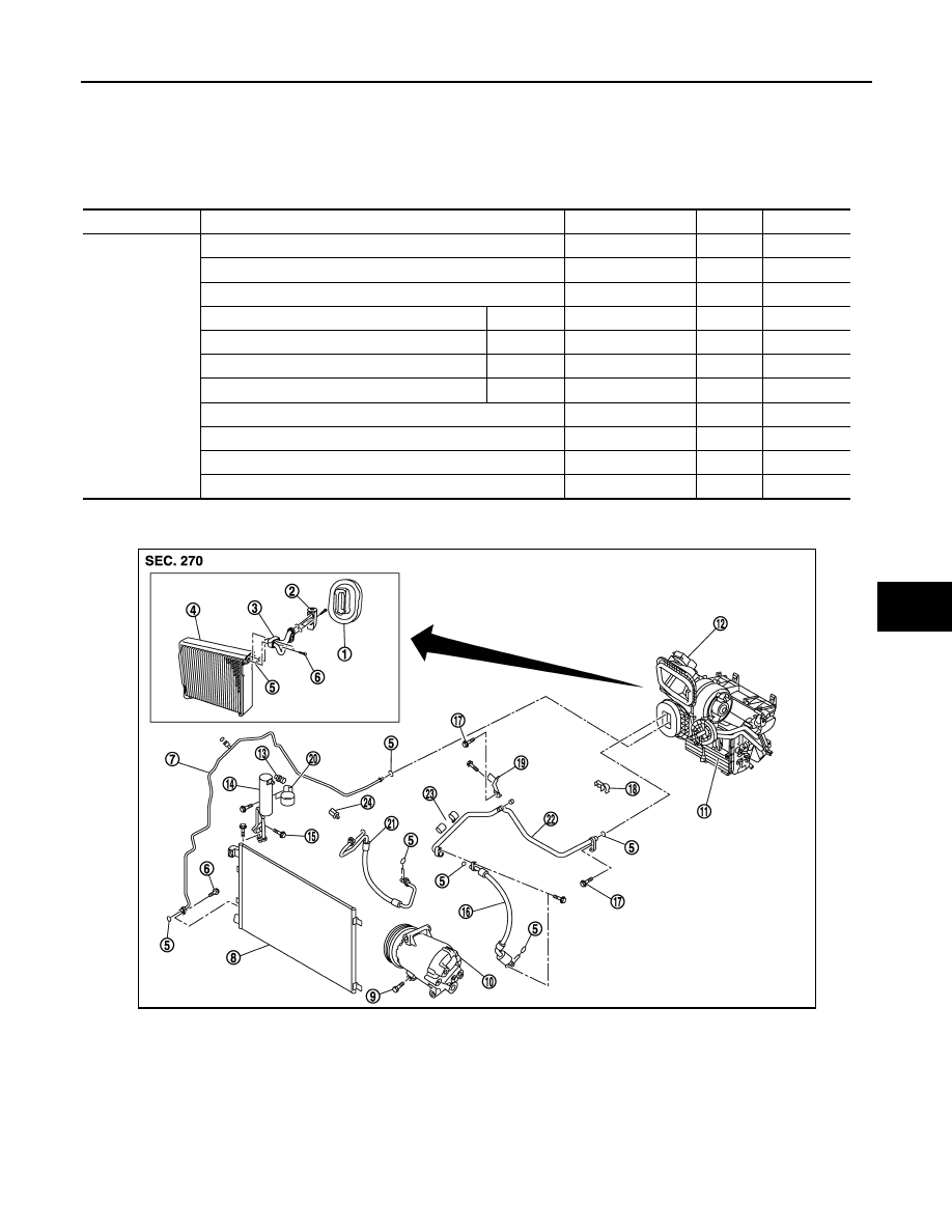
1.
Heater sealing
2.
Expansion valve
3.
Evaporator connector pipes
4.
Evaporator
5.
O-ring
6.
Connector pipe fixing bolt
7.
High pressure pipe
8.
Condenser assembly
9.
Fixing bolt
10.
Compressor
11.
Heater & cooling unit assembly
12. Heater & Blower unit assembly
13.
Refrigerant pressure sensor
14. Liquid tank
15. Liquid tank fixing screw
16.
Low pressure flexible hose
17. Fixing bolt
18. Pipes fixing clip
E1KIA0063GB
VTL-10
< PRECAUTION >
[AUTOMATIC AIR CONDITIONER]
PRECAUTIONS
CAUTION:
The new and former refrigerant connections use different O-ring configurations. Never confuse O-
rings since they are not interchangeable. If a wrong O-ring is installed, refrigerant may leak at the con-
nection.
O-Ring Part Numbers and Specifications
WARNING:
Make sure all refrigerant is discharged into the recycling equipment and the pressure in the system is
less than atmospheric pressure. Then gradually loosen the discharge side hose fitting and remove it.
CAUTION:
When replacing or cleaning refrigerant cycle components, observe the following.
• When the compressor is removed, store it in the same way at it is when mounted on the car. Failure
to do so will cause lubricant to enter the low-pressure chamber.
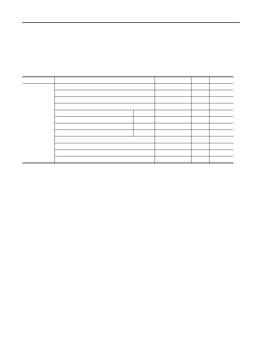
• When connecting tubes, always use a torque wrench and a back-up wrench.
• After disconnecting tubes, immediately plug all openings to prevent entry of dust and moisture.
• When installing an air conditioner in the vehicle, connect the pipes at the final stage of the operation.
Never remove the seal caps of pipes and other components until just before required for connection.
• Allow components stored in cool areas to warm to working area temperature before removing seal
caps. This prevents condensation from forming inside A/C components.
• Thoroughly remove moisture from the refrigeration system before charging the refrigerant.
• Always replace used O-rings.
• When connecting tube, apply lubricant to circle of the O-rings shown in illustration. Be careful not to
apply lubricant to threaded portion.
• O-ring must be closely attached to the groove portion of tube.
• When replacing the O-ring, be careful not to damage O-ring and tube.
• Connect tube until a click can be heard, then tighten the nut or bolt by hand. Make sure that the O-
ring is installed to tube correctly.
19.
Low & high pressure pipe bracket
20. Liquid tank fixing bracket
21. High pressure flexible hose
22.
Low pressure pipe
23. Low pressure pipe fixing clamp as-
sembly
24. Pipe mantening clip
Connection type
Piping connection point
Part number
QTY
O-ring size
New
Low pressure flexible hose to Low pressure pipe 2
92473 N8210
1
16
Low pressure pipe 2 to expansion valve
92473 N8210
1
16
High pressure flexible pipe 1 to condenser
92472 N8210
1
12
High pressure pipe 1 to expansion valve
92471 N8210
1
8
Low pressure pipe 1 and high pressure
Inlet
92475 71L00
1
12
Pipe 2 assembly to expansion valve
Outlet
92475 72L00
1
16
Low pressure pipe 1 and high pressure
Inlet
92475 71L00
1
12
Pipe 2 assembly to evaporator
Outlet
92475 72L00
1
16
High pressure pipe 1 to liquid tank
92471 N8210
1
8
Compressor to low pressure flexible hose
01-57-112
2
19
Compressor to high pressure flexible hose
01-57-112
2
12
Liquid tank to condenser
92473 N8210
2
16
Name
: Nissan A/C System Oil Type S
PRECAUTIONS
VTL-11
< PRECAUTION >
[AUTOMATIC AIR CONDITIONER]
C
D
E
F
G
H
J
K
L
M
A
B
VTL
N
O
P
• After connecting line, perform leak test and make sure that there is no leakage from connections.
When the refrigerant leaking point is found, disconnect that line and replace the O-ring. Then tighten
connections of seal seat to the specified torque.
Service Equipment
INFOID:0000000001093693
RECOVERY/RECYCLING EQUIPMENT
Be certain to follow the manufacturer’s manuals for machine operation and machine maintenance. Never
introduce any refrigerant other than that specified into the machine.
ELECTRICAL LEAK DETECTOR
Be certain to follow the manufacturer’s manuals for tester operation and tester maintenance.
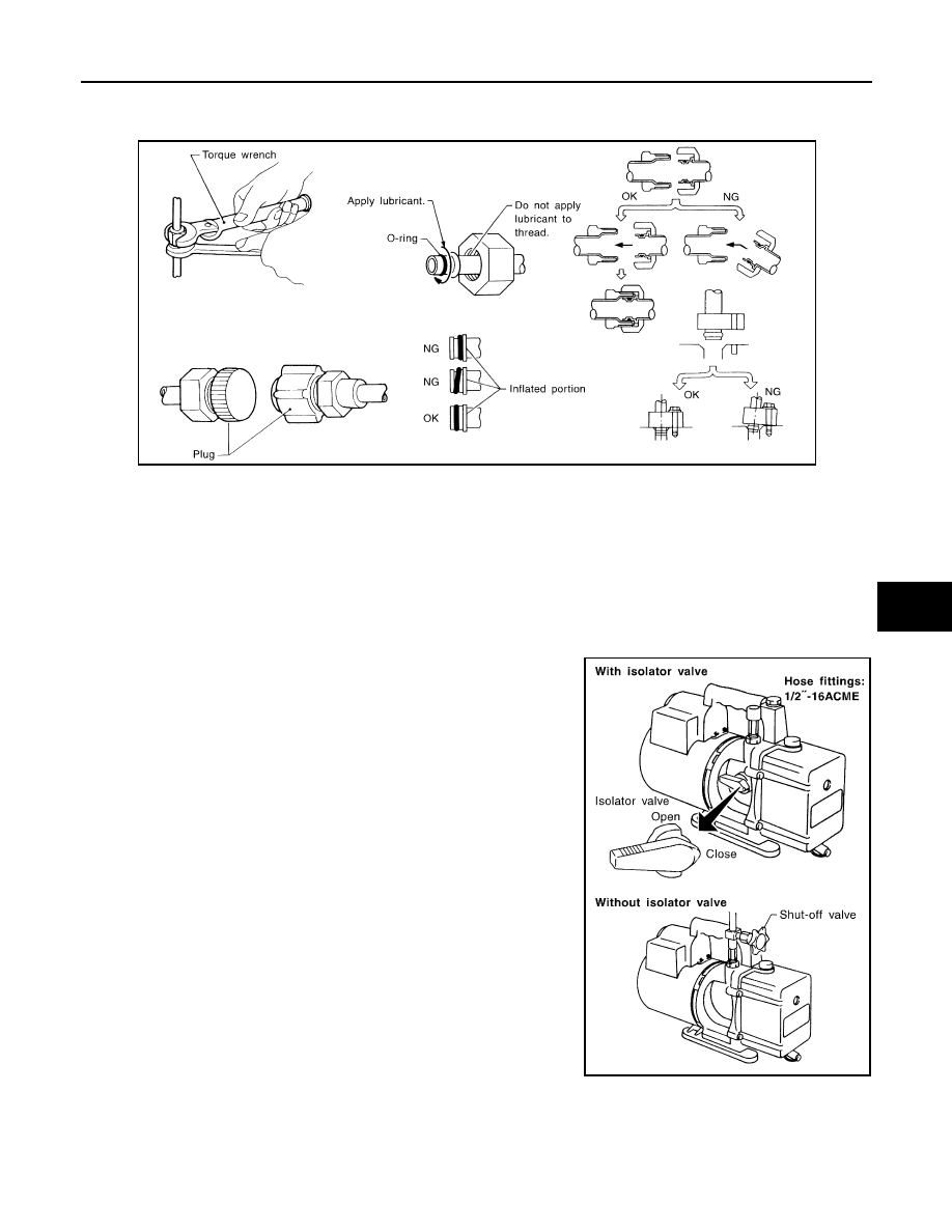
VACUUM PUMP
The lubricant contained inside the vacuum pump is not compatible
with the specified lubricant for HFC-134a (R-134a) A/C systems.
The vent side of the vacuum pump is exposed to atmospheric pres-
sure. So the vacuum pump lubricant may migrate out of the pump
into the service hose. This is possible when the pump is switched off
after evacuation (vacuuming) and hose is connected to it.
To prevent this migration, use a manual valve placed near the hose-
to-pump connection, as follows.
• Usually vacuum pumps have a manual isolator valve as part of the
pump. Close this valve to isolate the service hose from the pump.
• For pumps without an isolator, use a hose equipped with a manual
shut-off valve near the pump end. Close the valve to isolate the
hose from the pump.
• If the hose has an automatic shut-off valve, disconnect the hose
from the pump. As long as the hose is connected, the valve is open
and lubricating oil may migrate.
Some one-way valves open when vacuum is applied and close
under no vacuum condition. Such valves may restrict the pump’s
ability to pull a deep vacuum and are not recommended.
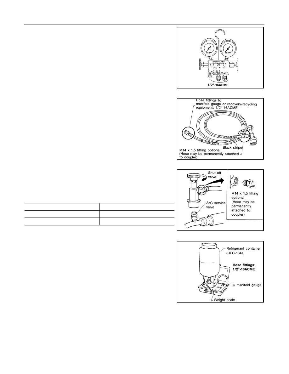
MANIFOLD GAUGE SET
RHA861F
RHA270DA
VTL-12
< PRECAUTION >
[AUTOMATIC AIR CONDITIONER]
PRECAUTIONS
Be certain that the gauge face indicates HFC-134a or R-134a. Be
sure the gauge set has 1/2
″
-16 ACME threaded connections for ser-
vice hoses. Confirm the set has been used only with refrigerant
HFC-134a (R-134a) and specified lubricants.
SERVICE HOSES
Be certain that the service hoses display the markings described
(colored hose with black stripe). All hoses must include positive shut-
off devices (either manual or automatic) near the end of the hoses
opposite to the manifold gauge.
SERVICE COUPLERS
Never attempt to connect HFC-134a (R-134a) service couplers to a
CFC-12 (R-12) A/C system. The HFC-134a (R-134a) couplers will
not properly connect to the CFC-12 (R-12) system. However, if an
improper connection is attempted, discharging and contamination
may occur.
REFRIGERANT WEIGHT SCALE
Verify that no refrigerant other than HFC-134a (R-134a) and speci-
fied lubricants have been used with the scale. If the scale controls
refrigerant flow electronically, the hose fitting must be 1/2
″
-16
ACME.
CHARGING CYLINDER
Using a charging cylinder is not recommended. Refrigerant may be vented into air from cylinder’s top valve
when filling the cylinder with refrigerant. Also, the accuracy of the cylinder is generally less than that of an
electronic scale or of quality recycle/recharge equipment.
SHA533D
RHA272D
Shut-off valve rotation
A/C service valve
Clockwise
Open
Counterclockwise
Close
RHA273D
RHA274D
Нет комментариевНе стесняйтесь поделиться с нами вашим ценным мнением.
Текст