Nissan Qashqai (2007-2010). Manual — part 1914
WCS-2
COMBINATION METER . . . . . . . . . . ...
COMBINATION METER : Diagnosis Procedure ....
BCM (BODY CONTROL MODULE) . . . . . . .
BCM (BODY CONTROL MODULE) : Diagnosis
Procedure . . . . . . . . . . . . . . . ...
METER BUZZER CIRCUIT . . . . . . . .
Description . . . . . . . . . . . . . . . ..
Component Function Check . . . . . . . . ...
Diagnosis Procedure . . . . . . . . . . . ..
SEAT BELT BUCKLE SWITCH SIGNAL CIR-
CUIT . . . . . . . . . . . . . . . . ...
Description . . . . . . . . . . . . . . . ..
Component Function Check . . . . . . . . ...
Diagnosis Procedure . . . . . . . . . . . ..
PARKING BRAKE SWITCH SIGNAL CIR-
CUIT . . . . . . . . . . . . . . . . ...
Description . . . . . . . . . . . . . . . ..
Diagnosis Procedure . . . . . . . . . . . ..
Component Inspection . . . . . . . . . . ....
WARNING CHIME SYSTEM . . . . . . . .
Wiring Diagram - WARNING CHIME - . . . . ....
ECU DIAGNOSIS . . . . . . . . . .
COMBINATION METER . . . . . . . . .
Reference Value . . . . . . . . . . . . . .
Wiring Diagram - METER - . . . . . . . . . .
Fail Safe . . . . . . . . . . . . . . . . .
DTC Index . . . . . . . . . . . . . . . ..
BCM (BODY CONTROL MODULE) . . . . ..
Reference Value . . . . . . . . . . . . . .
Wiring Diagram - BCM - . . . . . . . . . . ..
Fail Safe . . . . . . . . . . . . . . . . .
DTC Inspection Priority Chart . . . . . . . ...
DTC Index . . . . . . . . . . . . . . . ..
SYMPTOM DIAGNOSIS . . . . . . .
THE LIGHT REMINDER WARNING DOES
NOT SOUND . . . . . . . . . . . . . ..
Description . . . . . . . . . . . . . . . ..
Diagnosis Procedure . . . . . . . . . . . ...
Description . . . . . . . . . . . . . . . ..
Trouble diagnosis procedure . . . . . . . . ..
Description . . . . . . . . . . . . . . . ..
Diagnosis Procedure . . . . . . . . . . . ...
THE KEY WARNING DOES NOT SOUND . ...
Description . . . . . . . . . . . . . . . ..
Diagnosis Procedure . . . . . . . . . . . ...
PRECAUTION . . . . . . . . . . .

WCS
DIAGNOSIS AND REPAIR WORKFLOW
WCS-3
< BASIC INSPECTION >
C
D
E
F
G
H
I
J
K
L
M
B
A
O
P
BASIC INSPECTION
DIAGNOSIS AND REPAIR WORKFLOW
Work Flow
INFOID:0000000000953318
DETAILED FLOW
1.
OBTAIN INFORMATION ABOUT SYMPTOM
Interview the customer to obtain as much information as possible about the conditions and environment under
which the malfunction occurred.
>> GO TO 2.
2.
CHECK SYMPTOM
• Check the symptom based on the information obtained from the customer.
• Check if any other malfunctions are present.
>> GO TO 3.
3.
CHECK CONSULT-III SELF-DIAGNOSIS RESULTS
Connect CONSULT-III and perform self-diagnosis. Refer to
MWI-23, "CONSULT-III Function (METER/M&A)"
.
Are self-diagnosis results normal?
YES
>> GO TO 4.
NO
>> Repair or replace the malfunctioning parts and go to 5.
4.
NARROW DOWN MALFUNCTIONING PARTS THROUGH SYMPTOM DIAGNOSIS
Perform symptom diagnosis and repair or replace the identified malfunctioning parts.
>> GO TO 5.
5.
FINAL CHECK
Check that the warning buzzer in the combination meter operates normally.
Does it operate normally?
YES
>> INSPECTION END
NO
>> GO TO 1.
WCS-4
< FUNCTION DIAGNOSIS >
WARNING CHIME SYSTEM
FUNCTION DIAGNOSIS
WARNING CHIME SYSTEM
WARNING CHIME SYSTEM
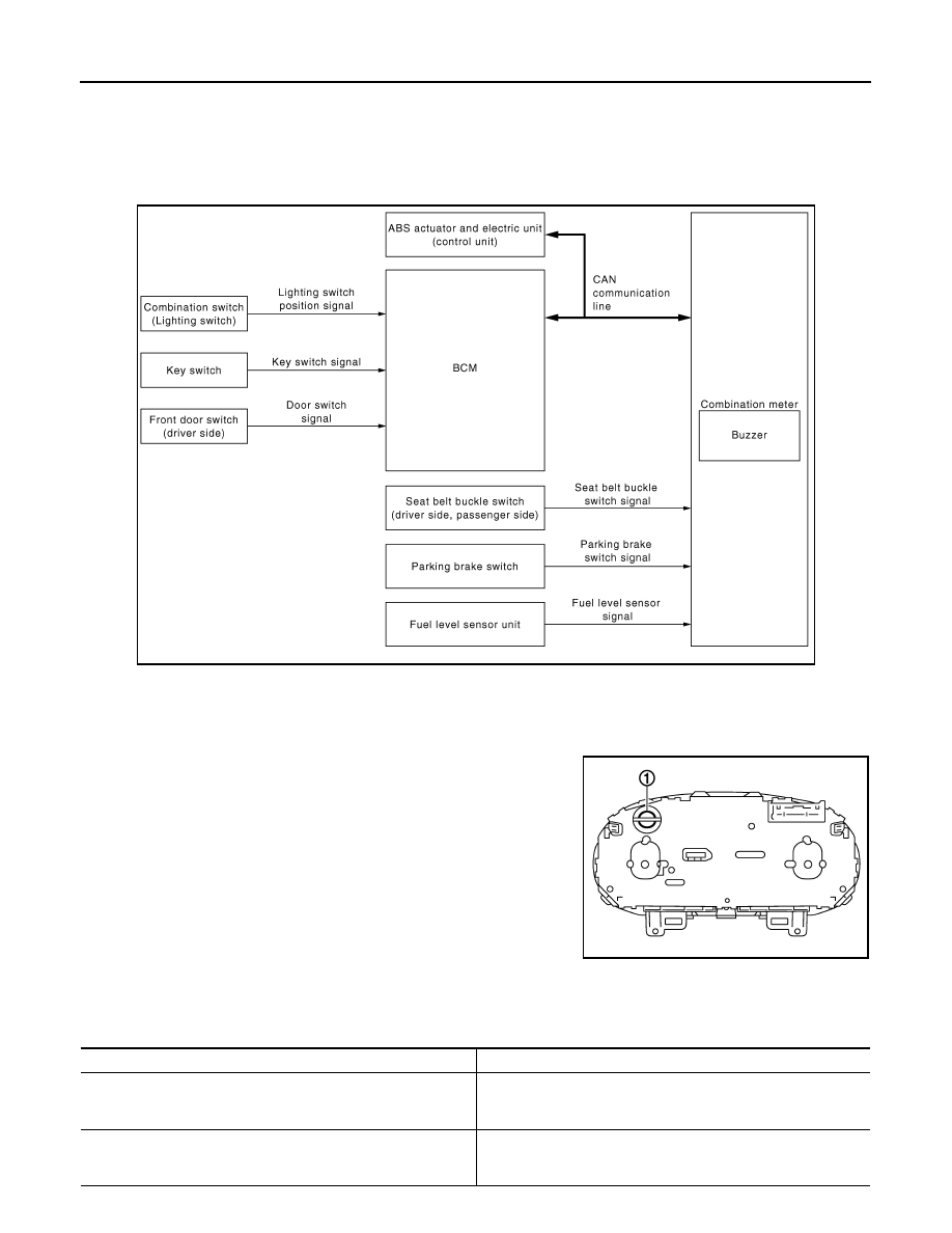
WARNING CHIME SYSTEM : System Diagram
INFOID:0000000000892392
WARNING CHIME SYSTEM : System Description
INFOID:0000000000892393
COMBINATION METER
• The buzzer (1) for the warning chime system is integrated in the
combination meter.
• The combination meter sounds the alarm buzzer installed in the
combination meter when receiving the buzzer output signal trans-
mitted from each unit.
BCM
BCM receives signals from various units and transmits a buzzer output signal to the combination meter via
CAN communication if it judges that the warning buzzer should be activated.
BCM warning function list
JSNIA0296GB
JSNIA0319ZZ
Warning functions
Signal name
Light reminder warning chime
• Ignition signal
• Lighting switch position signal
• Front door switch signal (driver side)
Key warning chime
• Ignition signal
• Key switch signal
• Front door switch signal (driver side)
WCS
WARNING CHIME SYSTEM
WCS-5
< FUNCTION DIAGNOSIS >
C
D
E
F
G
H
I
J
K
L
M
B
A
O
P
NOTE:
• Seat belt reminder warning, parking brake release warning and low fuel warning are judged by combination
meter.
• Intelligent key warning is judged by intelligent key unit.
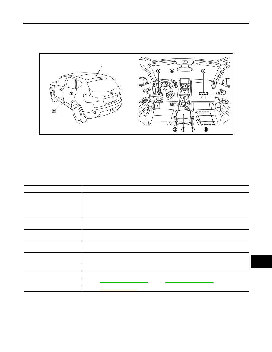
WARNING CHIME SYSTEM : Component Parts Location
INFOID:0000000000892394
WARNING CHIME SYSTEM : Component Description
INFOID:0000000000892395
LIGHT REMINDER WARNING CHIME
JSNIA0318ZZ
1.
Combination switch
(Lighting switch)
2.
Front door switch (driver side)
3.
Front seat belt buckle switch
(driver side)
4.
Parking brake switch
5.
Front seat belt buckle switch
(passenger side)
6.
Occupant detection unit
7.
BCM
8.
Key switch
Unit
Description
Combination meter
• Receives the buzzer output signal from BCM with the CAN communication line and sounds the
buzzer.
• Judges the remaining parking brake according to the vehicle speed signal received from the ABS
actuator and electric unit (control unit) via CAN communication and the parking brake switch sig-
nal from parking brake switch to sound the warning buzzer.
BCM
Transmits signals received from each unit to the combination meter with the CAN communication
line.
ABS actuator and electric unit
(control unit)
Transmits the vehicle speed signal to combination meter with the CAN communication line.
Front seat belt buckle switch
(Driver side, passenger side)
Transmits the seat belt buckle switch signal to the combination meter.
Combination switch (Lighting
switch)
Transmits the lighting switch signal to BCM.
Front door switch
Transmits the door switch signal to BCM.
Key switch
Transmits the ignition switch signal to BCM.
Fuel level sensor unit
Refer to
(4WD).
Parking brake switch
Refer to
.
Нет комментариевНе стесняйтесь поделиться с нами вашим ценным мнением.
Текст