Nissan Qashqai (2007-2010). Manual — part 1341
LIGHT & RAIN SENSOR
EXL-69
< COMPONENT DIAGNOSIS >
[XENON TYPE]
C
D
E
F
G
H
I
J
K
M
A
B
EXL
N
O
P
LIGHT & RAIN SENSOR
Description
INFOID:0000000000955457
• The light & rain sensor detects the outside brightness (lux), a rain-
drop and sensor conditions. And it transmits the signals to BCM by
the light & rain sensor serial link.
• BCM controls each function depending on the signals. And it
detects the light & rain sensor serial link error and the light & rain
sensor malfunction.
Component Function Check
INFOID:0000000000955458
1.
CHECK LIGHT & RAIN SENSOR BY CONSULT-III
CONSULT-III DATA MONITOR
1.
Turn the ignition switch ON.
2.
Select "LIT-SEN FAIL" of BCM (HEADLAMP) data monitor item.
3.
Turn the lighting switch AUTO.
4.
Start the engine.
5.
Check the monitor status.
Is it displayed with "OK"?
YES
>> Light & rain sensor is normal.
NO
>> Refer to
.
Diagnosis Procedure
INFOID:0000000000955459
1.
CHECK LIGHT & RAIN SENSOR POWER SUPPLY OUTPUT
1.
Turn the ignition switch OFF.
2.
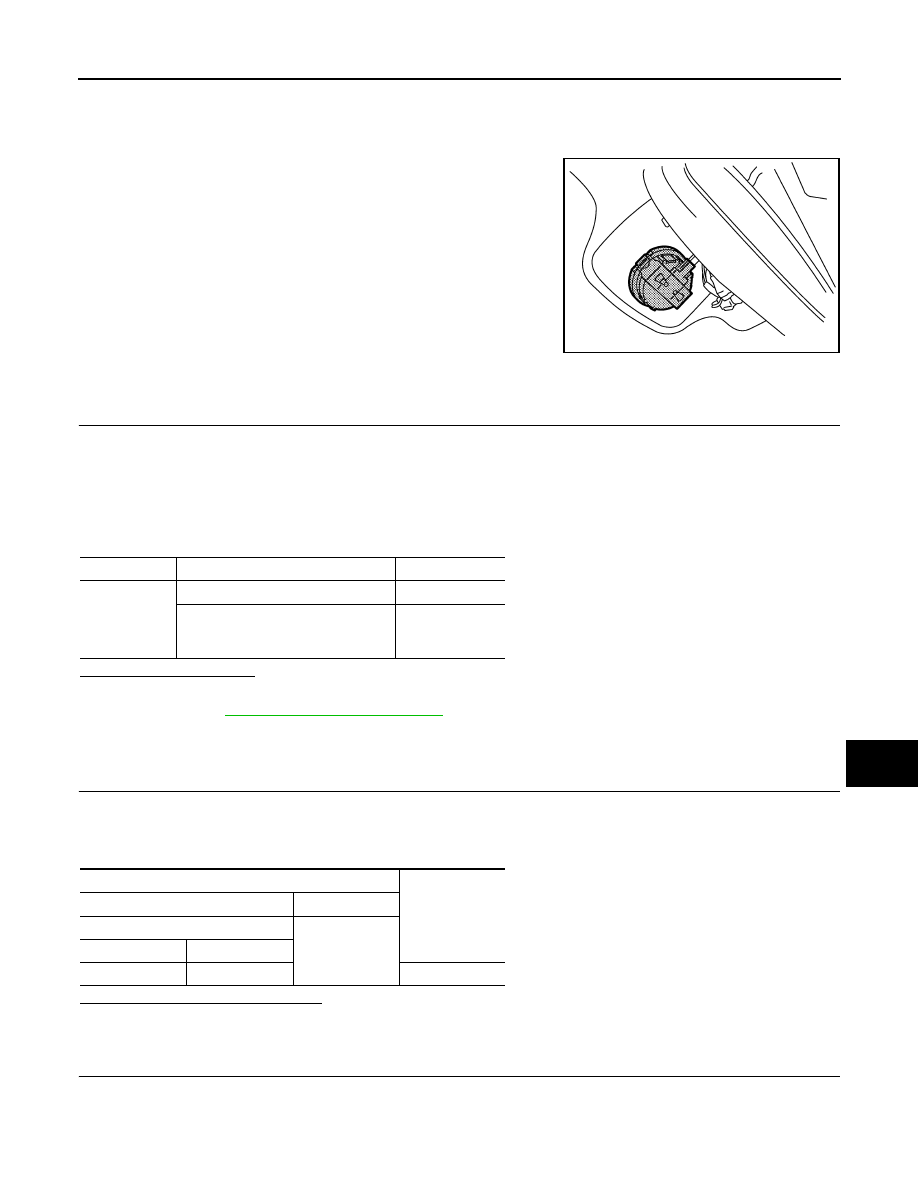
Disconnect the light & rain sensor connector.
3.
Check the voltage between the light & rain sensor harness connector and the ground.
Is the measurement value normal?
YES
>> GO TO 2.
NO
>> GO TO 3.
2.
CHECK LIGHT & RAIN SENSOR SIGNAL OUTPUT
Check the voltage between the light & rain sensor harness connector and the ground.
JSLIA0093ZZ
Monitor item
Condition
Status
LIT-SEN FAIL
Light & rain sensor is normal
OK
• Light & rain sensor inside abnor-
mality
• Light & rain sensor serial link error
NOTOK
Terminals
Voltage
(Approx.)
(+)
(
−
)
Light & rain sensor
Ground
Connector
Terminal
R13
1
12 V
EXL-70
< COMPONENT DIAGNOSIS >
[XENON TYPE]
LIGHT & RAIN SENSOR
Is the measurement value normal?
YES
>> GO TO 7.
NO
>> GO TO 5.
3.
CHECK LIGHT & RAIN SENSOR POWER SUPPLY OPEN CIRCUIT
1.
Disconnect BCM connector.
2.
Check continuity between the light & rain sensor harness connector and the BCM harness connector.
Does continuity exist?
YES
>> GO TO 4.
NO
>> Repair the harnesses or connectors.
4.
CHECK LIGHT & RAIN SENSOR POWER SUPPLY SHORT CIRCUIT
Check the continuity between the light & rain sensor harness connector and the ground.
Does continuity exist?
YES
>> Repair the harnesses or connectors.
NO
>> Replace BCM. Refer to
5.
CHECK LIGHT & RAIN SENSOR SIGNAL OPEN CIRCUIT
1.
Disconnect BCM connector.
2.
Check continuity between the light & rain sensor harness connector and the BCM harness connector.
Does continuity exist?
YES
>> GO TO 6.
NO
>> Repair the harnesses or connectors.
6.
CHECK LIGHT & RAIN SENSOR SIGNAL SHORT CIRCUIT
Check the continuity between the light & rain sensor harness connector and the ground.
Does continuity exist?
YES
>> Repair the harnesses or connectors.
NO
>> Replace BCM. Refer to
Terminals
Voltage
(Approx.)
(+)
(
−
)
Light & rain sensor
Ground
Connector
Terminal
R13
2
12 V
Light & rain sensor
BCM
Continuity
Connector
Terminal
Connector
Terminal
R13
1
M66
42
Existed
Light & rain sensor
Ground
Continuity
Connector
Terminal
R13
1
Not existed
Light & rain sensor
BCM
Continuity
Connector
Terminal
Connector
Terminal
R13
2
M66
17
Existed
Light & rain sensor
Ground
Continuity
Connector
Terminal
R13
2
Not existed
LIGHT & RAIN SENSOR
EXL-71
< COMPONENT DIAGNOSIS >
[XENON TYPE]
C
D
E
F
G
H
I
J
K
M
A
B
EXL
N
O
P
7.
CHECK LIGHT & RAIN SENSOR GROUND OPEN CIRCUIT
1.
Turn the ignition switch OFF.
2.
Check continuity between the light & rain sensor harness connector and the ground.
Does continuity exist?
YES
>> Replace the light & rain sensor.
NO
>> Repair the harnesses or connectors.
Light & rain sensor
Ground
Continuity
Connector
Terminal
R13
3
Existed
EXL-72
< COMPONENT DIAGNOSIS >
[XENON TYPE]
HAZARD SWITCH
HAZARD SWITCH
Component Function Check
INFOID:0000000000955461
1.
CHECK HAZARD SWITCH SIGNAL BY CONSULT-III
CONSULT-III DATA MONITOR
1.
Turn the ignition switch ON.
2.
Select "HAZARD SW" of BCM (FLASHER) data monitor item.
3.
With operating the hazard switch, check the monitor status.
Is the item status normal?
YES
>> Hazard switch circuit is normal.
NO
>> Refer to
.
Diagnosis Procedure
INFOID:0000000000955462
1.
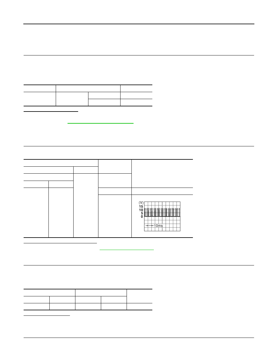
CHECK HAZARD SWITCH SIGNAL INPUT
With operating the hazard switch, check the voltage between the BCM harness connector and the ground.
Is the measurement value normal?
YES
>> Replace BCM. Refer to
NO
>> GO TO 2.
2.
CHECK HAZARD SWITCH SIGNAL OPEN CIRCUIT
1.
Turn the ignition switch OFF.
2.
Disconnect the hazard switch connector and BCM connector.
3.
Check continuity between the hazard switch harness connector and the BCM harness connector.
Does continuity exist?
YES
>> GO TO 3.
NO
>> Repair the harnesses or connectors.
3.
CHECK HAZARD SWITCH SIGNAL SHORT CIRCUIT
Check continuity between the hazard switch harness connector and the ground.
Monitor item
Condition
Monitor status
HAZARD SW
Hazard switch
ON
ON
OFF
OFF
Terminals
Condition
Voltage (Approx.)
(+)
(
−
)
BCM
Ground
Hazard switch
Connector
Terminal
M65
8
ON
0 V
OFF
JPMIA0154GB
Hazard switch
BCM
Continuity
Connector
Terminal
Connector
Terminal
M45
3
M65
8
Existed
Нет комментариевНе стесняйтесь поделиться с нами вашим ценным мнением.
Текст