Nissan Qashqai (2007-2010). Manual — part 911
HAC-4
General Refrigerant Precaution . . . . . . . .
Refrigerant Connection . . . . . . . . . . ..
Service Equipment . . . . . . . . . . . .
COMPRESSOR . . . . . . . . . . . ...
General Precautions . . . . . . . . . . . .
FLUORESCENT LEAK DETECTOR . . . .

DIAGNOSIS AND REPAIR WORKFLOW
HAC-5
< BASIC INSPECTION >
[AUTOMATIC AIR CONDITIONER]
C
D
E
F
G
H
J
K
L
M
A
B
HAC
N
O
P
BASIC INSPECTION
DIAGNOSIS AND REPAIR WORKFLOW
Work Flow
INFOID:0000000000954626
DETAILED FLOW
1.
LISTEN TO CUSTOMER COMPLAINT
Listen to customer complaint. (Get detailed information about the conditions and environment when the symp-
tom occurs.)
>> GO TO 2.
2.
VERIFY THE SYMPTOM WITH OPERATIONAL CHECK
Verify the symptom with operational check. Refer to
HAC-6, "Description & Inspection"
>> GO TO 3.
3.
GO TO APPROPRIATE TROUBLE DIAGNOSIS
Go to appropriate trouble diagnosis (Refer to
HAC-108, "Diagnosis Chart By Symptom"
>> GO TO 4.
4.
REPAIR OR REPLACE
Repair or replace the specific parts.
>> GO TO 5.
5.
FINAL CHECK
Final check.
Is the inspection result normal?
YES
>> CHECK OUT
NO
>> GO TO 3.
HAC-6
< BASIC INSPECTION >
[AUTOMATIC AIR CONDITIONER]
INSPECTION AND ADJUSTMENT
INSPECTION AND ADJUSTMENT
Description & Inspection
INFOID:0000000000954627
DESCRIPTION
The purpose of the operational check is to check if the individual system operates properly.
INSPECTION PROCEDURE
Memory Function
1.
Turn temperature control dial (driver side) clockwise until 30.0
°
C is displayed.
2.
Press ON/OFF switch.
3.
Turn ignition switch OFF.
4.
Turn ignition switch ON.
5.
Press AUTO switch.
6.
Confirm that the set temperature remains at previous temperature.
7.
Press ON/OFF switch.
If NG, go to trouble diagnosis procedure for
HAC-116, "Inspection procedure"
If OK, continue the check.
Blower
1.
Turn fan control dial clockwise. Blower should operate on low speed.
2.
Turn fan control dial clockwise again, and continue checking blower speed until all speeds are checked.
3.
Leave blower on max. speed.
If NG, go to trouble diagnosis procedure for
.
If OK, continue the check.
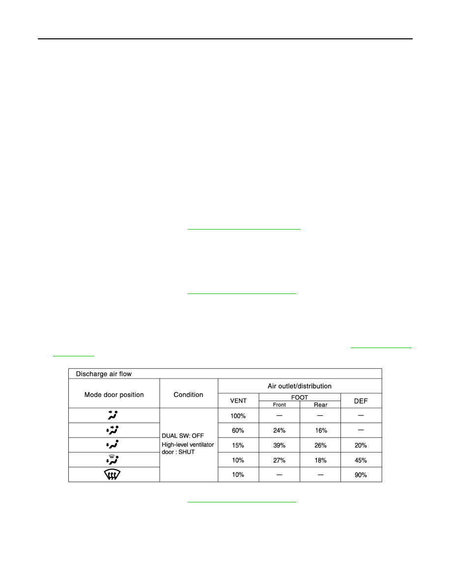
Discharge Air (MODE switch and DEF switch)
1.
Press MODE switches and DEF switch.
2.
Each position indicator should illuminate.
3.
Confirm that discharge air comes out according to the air distribution table. Refer to
.
If NG, go to trouble diagnosis procedure for
.
If OK, continue the check.
NOTE:
Confirm that the magnet clutch is engaged (sound or visual inspection) and intake door position is at FRE
when the D/F or DEF is selected.
Discharge Air (High-level ventilator switch)
1.
Press high-level ventilator switch. High-level ventilator switch indicator should illuminate.
Conditions
: Engine running at normal operating temperature
JPIIA0082GB

INSPECTION AND ADJUSTMENT
HAC-7
< BASIC INSPECTION >
[AUTOMATIC AIR CONDITIONER]
C
D
E
F
G
H
J
K
L
M
A
B
HAC
N
O
P
2.
Confirm that discharge air comes out.
3.
Press high-level ventilator switch again. High-level ventilator indicator should not illuminate.
If NG, go to trouble diagnosis procedure for
.
If OK, continue the check.
Intake Air
1.
Press recirculation (REC) switch. Recirculation indicator should illuminate.
2.
Press fresh (FRE) switch. Fresh indicator should illuminate.
3.
Listen for intake door position change. (Slight change of blower sound can be heard.)
If NG, go to trouble diagnosis procedure for
.
If OK, continue the check.
NOTE:
Confirm that the magnet clutch is engaged (sound or visual inspection) and intake door position is at FRE
when the D/F or DEF is selected.
Temperature Decrease
1.
Turn temperature control dial (driver side) counterclockwise until 16.0
°
C is displayed.
2.
Check for cold air at discharge air outlets.
If NG, go to trouble diagnosis procedure for
HAC-109, "Inspection procedure"
If OK, continue the check.
Temperature Increase
1.
Turn temperature control dial (driver side) clockwise until 30.0
°
C is displayed.
2.
Check for hot air at discharge air outlets.
If NG, go to trouble diagnosis procedure for
HAC-111, "Inspection procedure"
If OK, continue the check.
A/C Switch
1.
Press AUTO switch and A/C switch.
2.
A/C switch indicator will turn ON.
• Confirm that the magnet clutch engages (sound or visual inspection).
Auto Mode
1.
Press AUTO switch and A/C switch.
2.
AUTO switch indicator will turn ON.
• Confirm that discharge air and blower speed will depend on ambient, in-vehicle, and set temperatures.
If NG, go to trouble diagnosis procedure for
, then if necessary, trouble diagno-
If all operational checks are OK (symptom cannot be duplicated), go to Incident Simulation Tests in
and perform tests as outlined to simulate driving conditions environment. If symptom appears,
refer to
HAC-108, "Diagnosis Chart By Symptom"
and perform applicable trouble diagnosis procedures.
AUXILIARY MECHANISM
Temperature Setting Trimmer
The trimmer compensates for differences in range of
±
3
°
C between temperature setting (displayed digitally)
and temperature felt by customer.
Operating procedures for this trimmer are as follows:
1.
Begin self-diagnosis STEP-5 mode. Refer to
HAC-27, "Diagnosis Description"
2.
Turn fan control dial clockwise to set system in auxiliary mode.
3.
Display shows “61” in auxiliary mechanism. It takes approximately 3 seconds to enable setting operation.
4.
Turn temperature control dial (driver side) as desired. Temperature will change at a rate of 0.5
°
C each
time a dial is turned.
CAUTION:
• A decimal point is not indicated on the display.
Нет комментариевНе стесняйтесь поделиться с нами вашим ценным мнением.
Текст