Nissan Qashqai (2007-2010). Manual — part 597
ROAD TEST
TM-323
< ON-VEHICLE MAINTENANCE >
[CVT: RE0F10A]
C
E
F
G
H
I
J
K
L
M
A
B
TM
N
O
P
6.
CHECK ENGINE BRAKE FUNCTION
Check engine brake.
Does engine braking effectively reduce speed in M1 position?
YES
>> 1.
Stop the vehicle.
2.
Perform self-diagnosis. Refer to
TM-216, "CONSULT-III Function (TRANSMISSION)"
.
NO
>> Refer to
. Then continue trouble diagnosis.
TM-324
< ON-VEHICLE MAINTENANCE >
[CVT: RE0F10A]
CVT POSITION
CVT POSITION
Inspection and Adjustment
INFOID:0000000000914708
INSPECTION
1.
Place selector lever in “P” position, and turn ignition switch ON (engine stop).
2.
Make sure that selector lever can be shifted to other than “P” position when brake pedal is depressed.
Also make sure that selector lever can be shifted from “P” position only when brake pedal is depressed.
3.
Move the selector lever and check for excessive effort, sticking, noise or rattle.
4.
Confirm the selector lever stops at each position with the feel of engagement when it is moved through all
the positions. Check that the actual position of the selector lever matches the position shown by the shift
position indicator and the manual lever on the transaxle.
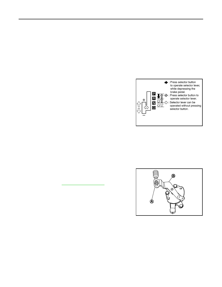
5.
The method of operating the selector lever to individual posi-
tions correctly should be as shown.
6.
When selector button is pressed in “P”, “R”, or “N” position with-
out applying forward/backward force to selector lever, check but-
ton operation for sticking.
7.
Confirm the back-up lamps illuminate only when selector lever is
placed in the “R” position. Confirm the back-up lamps do not illu-
minate when the selector lever is pushed toward the “R” position
when in the “P” or “N” position.
8.
Confirm the engine can only be started with the selector lever in
the “P” and “N” positions.
9.
Make sure transaxle is locked completely in “P” position.
10. When selector lever is set to manual shift gate, make sure that manual mode is displayed on combination
meter.
Shift selector lever to “+” and “–” sides, and check that set shift position changes.
ADJUSTMENT
1.
Place selector lever in “ P” position.
CAUTION:
Turn wheels more than 1/4 rotations and apply the park lock.
2.
Loosen nut (A) and place manual lever (B) in “P” position.
CAUTION:
Never apply any force to the manual lever.
3.
Tighten nut. Refer to
.
CAUTION:
Fix the manual lever when tightening.
SCIA6760E
JPDIA0313ZZ
TRANSMISSION CONTROL MODULE
TM-325
< ON-VEHICLE REPAIR >
[CVT: RE0F10A]
C
E
F
G
H
I
J
K
L
M
A
B
TM
N
O
P
ON-VEHICLE REPAIR
TRANSMISSION CONTROL MODULE
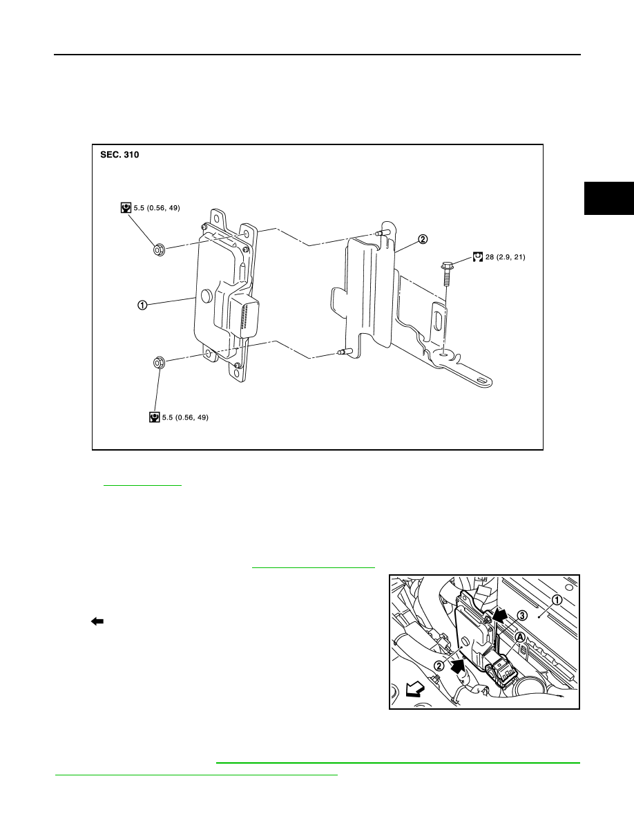
Exploded View
INFOID:0000000000914709
Removal and Installation
INFOID:0000000000914710
REMOVAL
1.
Disconnect the battery cable from negative terminal.
2.
Remove the Air duct (inlet). Refer to
.
3.
Disconnect the TCM harness connector (A).
4.
Remove the TCM (2) from the bracket (3).
INSTALLATION
Note the following, and install in the reverse order of removal.
CAUTION:
After TCM is replaced, refer to
TM-189, "ADDITIONAL SERVICE WHEN REPLACING CONTROL UNIT :
Service After Replacing TCM and Transaxle Assembly"
.
1.
TCM
2.
Bracket
Refer to
JPDIA0064GB
: Vehicle front
: Nut
1
: Battery
JPDIA0065ZZ
TM-326
< ON-VEHICLE REPAIR >
[CVT: RE0F10A]
CONTROL DEVICE
CONTROL DEVICE
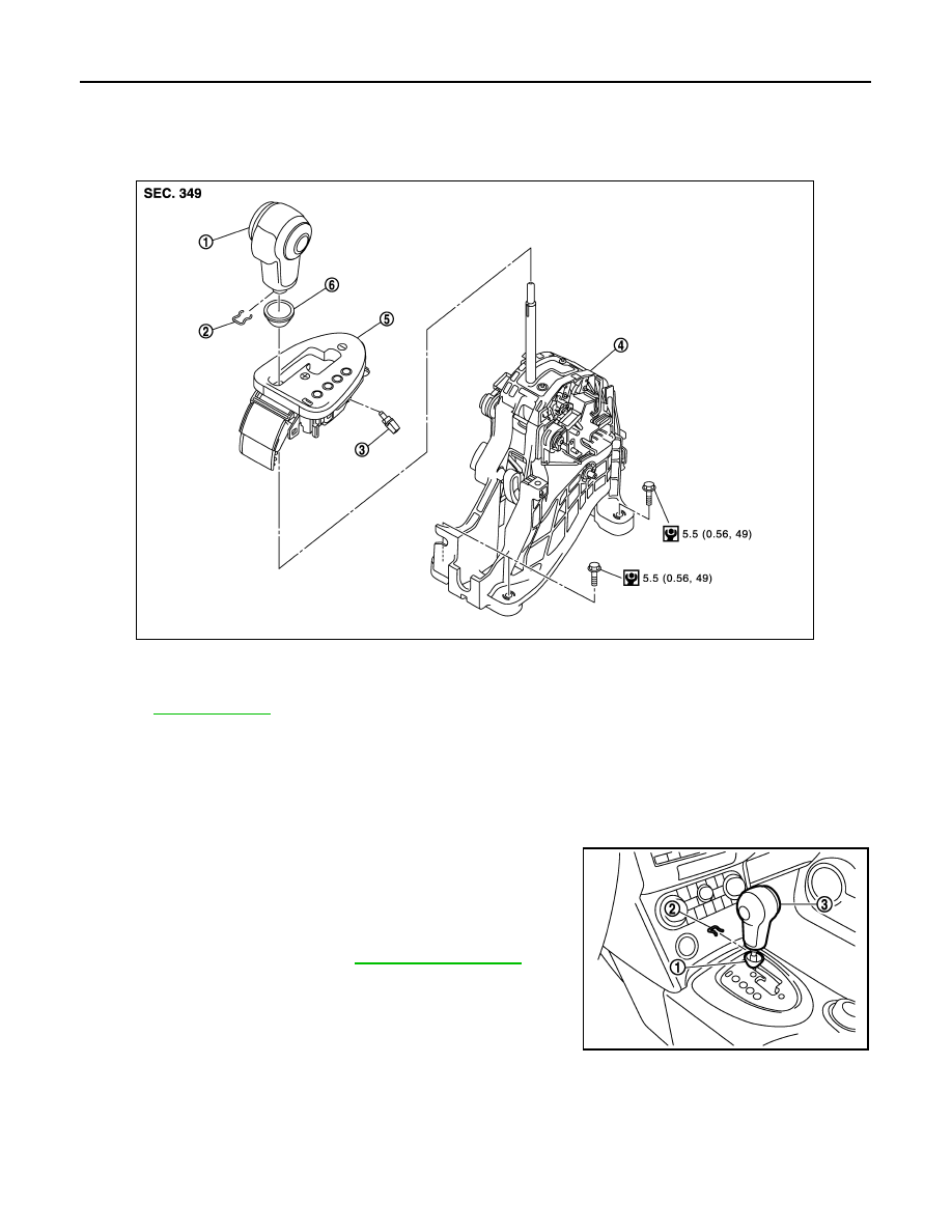
Exploded View
INFOID:0000000000914711
Removal and Installation
INFOID:0000000000914712
REMOVAL
1.
Disconnect the battery cable from the negative terminal.
2.
Move selector lever to “N” position.
3.
Remove knob cover (1) below selector lever downward.
CAUTION:
Be careful not to damage the knob cover.
4.
Pull lock pin (2) out of selector lever knob (3).
5.
Remove selector lever knob and knob cover.
6.
Remove center console. Refer to
1.
Selector lever knob
2.
Lock pin
3.
Position lamp
4
Control device assembly
5.
Position indicator plate
6.
Knob cover
Refer to
for symbols in the figure.
JPDIA0318GB
JPDIA0073ZZ
Нет комментариевНе стесняйтесь поделиться с нами вашим ценным мнением.
Текст