Nissan Qashqai (2007-2010). Manual — part 514
CLUTCH MASTER CYLINDER
CL-11
< ON-VEHICLE REPAIR >
C
E
F
G
H
I
J
K
L
M
A
B
CL
N
O
P
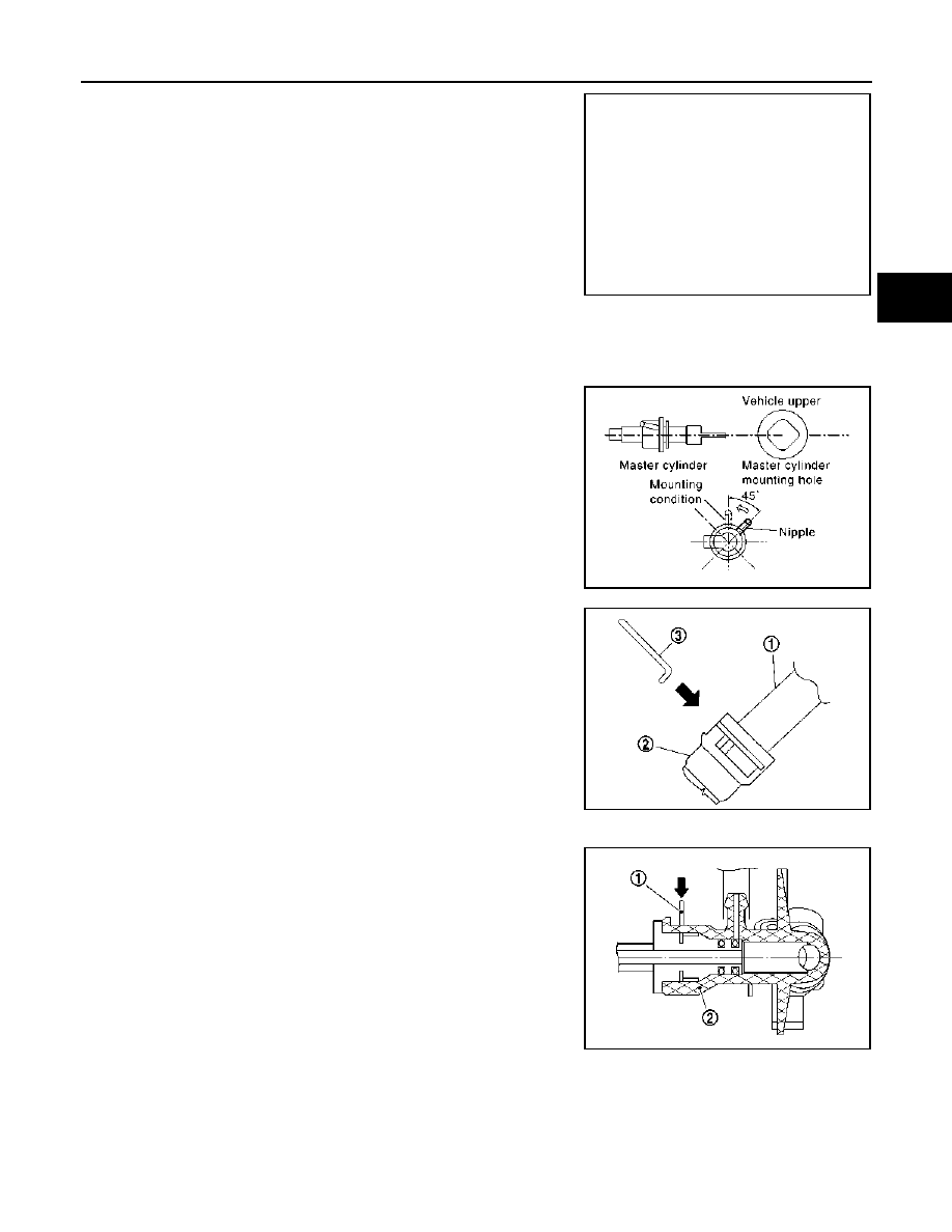
6.
Remove lock pin (1) from connector of master cylinder (2) and
separate clutch tube (3).
7.
Rotate master cylinder assembly clockwise by 45
°
and then
remove master cylinder assembly from the vehicle.
INSTALLATION
CAUTION:
Keep painted surface on the body or other parts free of clutch fluid. If it spills, wipe up immediately
and wash the affected area with water.
1.
Tilt master cylinder assembly clockwise by 45
°
and insert it to
the mounting hole. Rotate counterclockwise and secure it. At
this time, nipple is upward of the vehicle.
2.
Install master cylinder rod end to clutch pedal assembly.
3.
Install hose to reservoir tank assembly and master cylinder
assembly.
CAUTION:
Set hose with painted mark facing upward.
4.
Install clutch tube (1) into connector of master cylinder assembly
(2) until it stops.
5.
Install lock pin (3) into connector of master cylinder assembly
until it stops.
6.
Fill new clutch fluid according to the following.
a.
Fill reservoir tank assembly with new clutch fluid.
b.
Connect a transparent vinyl hose to air bleeder of bleeding con-
nector.
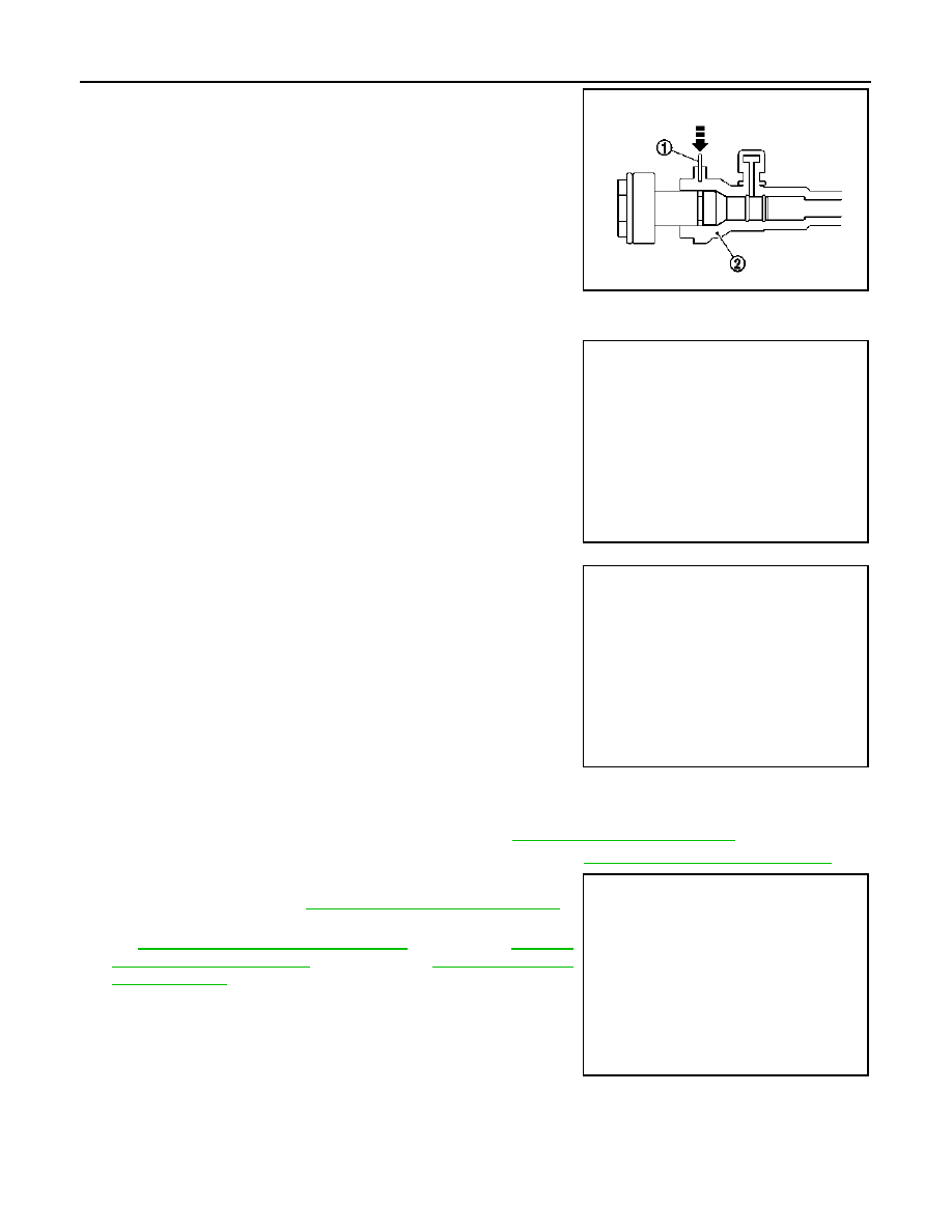
c.
Push the lock pin (1) of the bleeding connector (2).
• RS5F92R
PCIB1497E
SCIA1286E
PCIB1500E
PCIB1495E
CL-12
< ON-VEHICLE REPAIR >
CLUTCH MASTER CYLINDER
• RS6F94R and RS6F52A
d.
Slide clutch tube (1) in the direction of the arrow as shown in the figure.
• RS5F92R
• RS6F94R and RS6F52A
e.
Depress clutch pedal slowly to full stroke and then release it.
Repeat this until new clutch fluid comes out.
CAUTION:
• Hold it to prevent releasing clutch tube from bleeding
connector when fluid pressure is applied in the tube.
• Monitor clutch fluid level in reservoir tank to make sure it
does not empty.
f.
Place clutch tube (1) and lock pin back into position with clutch pedal depressed.
g.
Bleed the air from the clutch hydraulic system. Refer to
CL-6, "Air Bleeding Procedure"
.
7.
After completing this procedure, inspect for clutch pedal. Refer to
CL-5, "Inspection and Adjustment"
.
8.
Install the bracket (1) and then connect the connectors (A).
9.
Install the battery. Refer to
PG-118, "Removal and Installation"
10. Install the air cleaner case and air duct (inlet) or air ducts. Refer
to
EM-27, "Removal and Installation"
(K9K).
JPDIB0041ZZ
Dimension “A”
: 5 mm (0.20 in)
JPDIB0045ZZ
2
: Clutch housing
Dimension “A”
: 10 mm (0.39 in)
JPDIB0042ZZ
JPDIA0240ZZ
CLUTCH PIPING
CL-13
< ON-VEHICLE REPAIR >
C
E
F
G
H
I
J
K
L
M
A
B
CL
N
O
P
CLUTCH PIPING
Exploded View
INFOID:0000000001043518
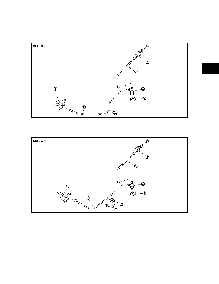
RS5F92R
RS6F94R and RS6F52A
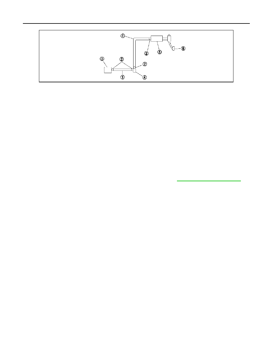
Hydraulic Layout
INFOID:0000000001043519
JPDIB0036ZZ
1.
CSC (Concentric Slave Cylinder)
2.
Clutch tube
3.
Bracket
4.
Clutch damper
5.
Master cylinder assembly
JPDIB0037ZZ
1.
CSC (Concentric Slave Cylinder)
2.
Clutch tube
3.
Bracket
4.
Clutch damper
5.
Master cylinder assembly
CL-14
< ON-VEHICLE REPAIR >
CLUTCH PIPING
Removal and Installation
INFOID:0000000001043520
CAUTION:
Keep painted surface on the body or other parts free of clutch fluid. If it spills, wipe up immediately
and wash the affected area with water.
REMOVAL
Refer to the figure for removal procedure.
INSTALLATION
Refer to the figure for installation procedure.
• When installing clutch tube to connector of CSC, connector of clutch damper and connector of master cylin-
der, push it as far as it goes.
• When installing lock pin to connector of CSC, connector of clutch damper and connector of master cylinder,
push it as far as it goes.
• After installation, bleed the air from the clutch hydraulic system. Refer to
CL-6, "Air Bleeding Procedure"
.
CAUTION:
Never scratch or damage clutch hose.
1.
Clutch tube
2.
Lock pin
3.
CSC (Concentric Slave Cylinder)
4.
Clutch damper
5.
Master cylinder assembly
6.
Clutch pedal assembly
PCIB1499E
Нет комментариевНе стесняйтесь поделиться с нами вашим ценным мнением.
Текст