Nissan Qashqai (2007-2010). Manual — part 1377
POWER SUPPLY AND GROUND CIRCUIT
EXL-213
< COMPONENT DIAGNOSIS >
[HALOGEN TYPE]
C
D
E
F
G
H
I
J
K
M
A
B
EXL
N
O
P
COMPONENT DIAGNOSIS
POWER SUPPLY AND GROUND CIRCUIT
BCM (BODY CONTROL MODULE)
BCM (BODY CONTROL MODULE) : Diagnosis Procedure
INFOID:0000000001099350
1.
CHECK FUSES AND FUSIBLE LINK
Check that the following fuses and fusible link are not fusing.
Is the fuse fusing?
YES
>> Replace the blown fuse or fusible link after repairing the affected circuit if a fuse or fusible link is
blown.
NO
>> GO TO 2.
2.
CHECK POWER SUPPLY CIRCUIT
1.
Turn ignition switch OFF.
2.
Disconnect BCM connectors.
3.
Check voltage between BCM harness connector and ground.
Is the measurement value normal?
YES
>> GO TO 3.
NO
>> Repair harness or connector.
3.
CHECK GROUND CIRCUIT
Check continuity between BCM harness connector and ground.
Does continuity exist?
YES
>> INSPECTION END
NO
>> Repair harness or connector.
IPDM E/R (INTELLIGENT POWER DISTRIBUTION MODULE ENGINE ROOM)
IPDM E/R (INTELLIGENT POWER DISTRIBUTION MODULE ENGINE ROOM) : Di-
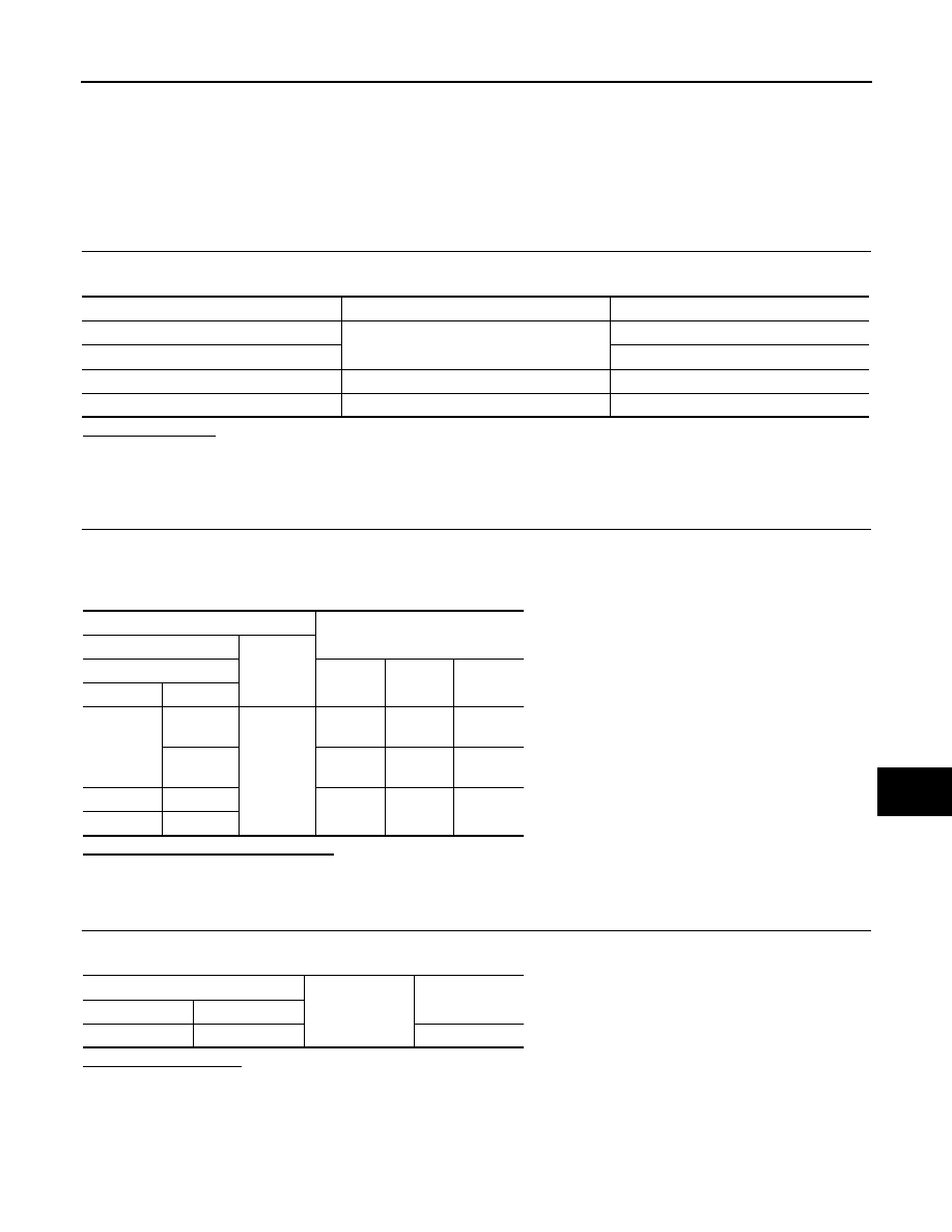
Terminal No.
Signal name
Fuses and fusible link No.
41
Battery power supply
9
57
J
37
ACC power supply
5
38
Ignition power supply
4
Terminals
Ignition switch position
(+)
(
−
)
BCM
OFF
ACC
ON
Connector
Terminal
M65
37
Ground
Approx.
0 V
Battery
voltage
Battery
voltage
38
Approx.
0 V
Approx.
0 V
Battery
voltage
M66
41
Battery
voltage
Battery
voltage
Battery
voltage
M67
57
BCM
Ground
Continuity
Connector
Terminal
M67
55
Existed
EXL-214
< COMPONENT DIAGNOSIS >
[HALOGEN TYPE]
POWER SUPPLY AND GROUND CIRCUIT
agnosis Procedure
INFOID:0000000001099351
1.
CHECK FUSIBLE LINK
Check that the following IPDM E/R fusible link is not blown.
Is the fusible link fusing?
YES
>> Replace the blown fusible link after repairing the affected circuit if a fusible link is blown.
NO
>> GO TO 2.
2.
CHECK POWER SUPPLY CIRCUIT
1.
Turn ignition switch OFF.
2.
Disconnect IPDM E/R connector.
3.
Check voltage between IPDM E/R harness connector and ground.
Is the measurement value normal?
YES
>> GO TO 3.
NO
>> Repair harness or connector.
3.
CHECK GROUND CIRCUIT
1.
Disconnect IPDM E/R connectors.
2.
Check continuity between IPDM E/R harness connectors and ground.
Does continuity exist?
YES
>> INSPECTION END
NO
>> Repair harness or connector.
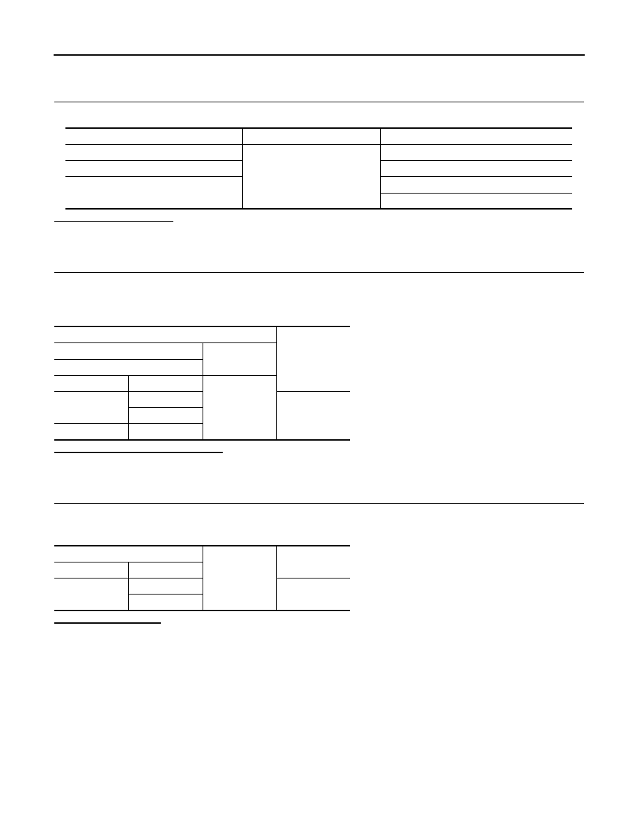
Terminal No.
Signal name
Fusible link No.
1
Battery power supply
E
2
C
53
L (except HR engine models)
M (HR engine models)
Terminals
Voltage
(Approx.)
(+)
(
−
)
IPDM E/R
Connector
Terminal
Ground
E9
1
Battery voltage
2
E14
53
IPDM E/R
Ground
Continuity
Connector
Terminal
E10
5
Exist
6

EXTERIOR LAMP FUSE
EXL-215
< COMPONENT DIAGNOSIS >
[HALOGEN TYPE]
C
D
E
F
G
H
I
J
K
M
A
B
EXL
N
O
P
EXTERIOR LAMP FUSE
Description
INFOID:0000000001099352
Fuse list
Diagnosis Procedure
INFOID:0000000001099353
1.
CHECK FUSE
Check that the following fuses are not fusing.
Is the fuse fusing?
YES
>> Repair the applicable circuit. And then replace the fuse.
NO
>> The fuse is normal.
Unit
Location
Fuse No.
Capacity
Headlamp HI (LH)
IPDM E/R
#48
10 A
Headlamp HI (RH)
IPDM E/R
#47
10 A
Headlamp LO (LH)
IPDM E/R
#46
15 A
Headlamp LO (RH)
IPDM E/R
#45
15 A
Front fog lamp
IPDM E/R
#43
15 A
• Parking lamp
• Tail lamp
• License plate lamp
• Each illumination
IPDM E/R
#49
10 A
Stop lamp
FUSE BLOCK (J/B)
#11
10 A
Back-up lamp
M/T models
IPDM E/R
#54
10 A
CVT models
IPDM E/R
#55
10 A
Unit
Location
Fuse No.
Capacity
Headlamp HI (LH)
IPDM E/R
#48
10 A
Headlamp HI (RH)
IPDM E/R
#47
10 A
Headlamp LO (LH)
IPDM E/R
#46
15 A
Headlamp LO (RH)
IPDM E/R
#45
15 A
Front fog lamp
IPDM E/R
#43
15 A
• Parking lamp
• Tail lamp
• License plate lamp
• Each illumination
IPDM E/R
#49
10 A
Stop lamp
FUSE BLOCK (J/
B)
#11
10 A
Back-up
lamp
M/T models
IPDM E/R
#54
10 A
CVT models
IPDM E/R
#55
10 A
EXL-216
< COMPONENT DIAGNOSIS >
[HALOGEN TYPE]
HEADLAMP (HI) CIRCUIT
HEADLAMP (HI) CIRCUIT
Component Function Check
INFOID:0000000001099354
1.
CHECK HEADLAMP (HI) OPERATION
IPDM E/R AUTO ACTIVE TEST
1.
Start IPDM E/R auto active test. Refer to
PCS-9, "Diagnosis Description"
.
2.
Check that the headlamp switches to the high beam.
CONSULT-III ACTIVE TEST
1.
Select "EXTERNAL LAMP" of IPDM E/R active test item.
2.
With operating the test items, check that the headlamp (HI) is turned ON.
NOTE:
ON/OFF is repeated 1 second each.
Is the headlamp (HI) turned ON?
YES
>> Headlamp (HI) circuit is normal.
NO
>> Refer to
EXL-216, "Diagnosis Procedure"
.
Diagnosis Procedure
INFOID:0000000001099355
1.
CHECK HEADLAMP (HI) OUTPUT VOLTAGE
CONSULT-III ACTIVE TEST
1.
Turn the ignition switch OFF.
2.
Disconnect the front combination lamp connector.
3.
Turn the ignition switch ON.
4.
Select "EXTERNAL LAMP" of IPDM E/R active test item.
5.
With operating the test items, check the voltage between the IPDM E/R harness connector and the
ground.
Is the measurement value normal?
YES
>> GO TO 2.
NO
>> GO TO 3.
2.
CHECK HEADLAMP (HI) OPEN CIRCUIT
1.
Turn the ignition switch OFF.
2.
Disconnect IPDM E/R connector.
3.
Check continuity between the IPDM E/R harness connector and the front combination lamp harness con-
nector.
Does continuity exist?
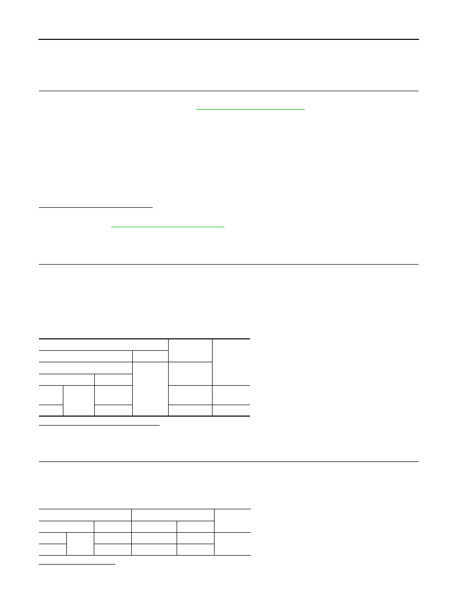
HI
: Headlamp (HI) ON
OFF
: Headlamp (HI) OFF
Terminals
Condition
Voltage
(Approx.)
(+)
(
−
)
IPDM E/R
Ground
External
lamp
Connector
Terminal
RH
E13
45
HI
Battery
voltage
LH
46
OFF
0 V
IPDM E/R
Front combination lamp
Continuity
Connector
Terminal
Connector
Terminal
RH
E13
45
E45
2
Existed
LH
46
E26
2
Нет комментариевНе стесняйтесь поделиться с нами вашим ценным мнением.
Текст