Nissan Qashqai (2007-2010). Manual — part 920
HAC-40
< FUNCTION DIAGNOSIS >
[AUTOMATIC AIR CONDITIONER]
AIR MIX DOOR CONTROL SYSTEM
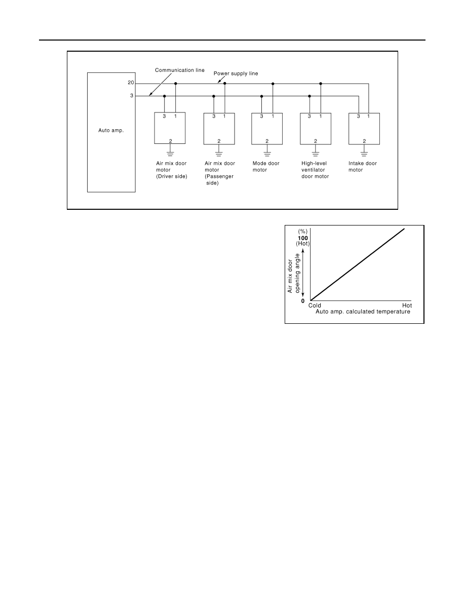
LAN System Circuit
Air Mix Door Control Specification
When ignition switch is ON, auto amp. continuously and automati-
cally controls temperatures regardless of air conditioner operational
condition. When setting a target temperature with temperature con-
trol dial, auto amp. corrects the set temperature and decides a target
air mix door opening angle. Auto amp. controls air mix door accord-
ing to the target air mix door opening angle and current air mix door
opening angle in order to keep an optimum air mix door opening
angle. When a temperature is set at 16.0
°
C, air mix door is fixed at
full cold, and when a temperature is set at 30.0
°
C, it is set at full hot.
JPIIA0122GB
RHA457H
INTAKE DOOR CONTROL SYSTEM
HAC-41
< FUNCTION DIAGNOSIS >
[AUTOMATIC AIR CONDITIONER]
C
D
E
F
G
H
J
K
L
M
A
B
HAC
N
O
P
INTAKE DOOR CONTROL SYSTEM
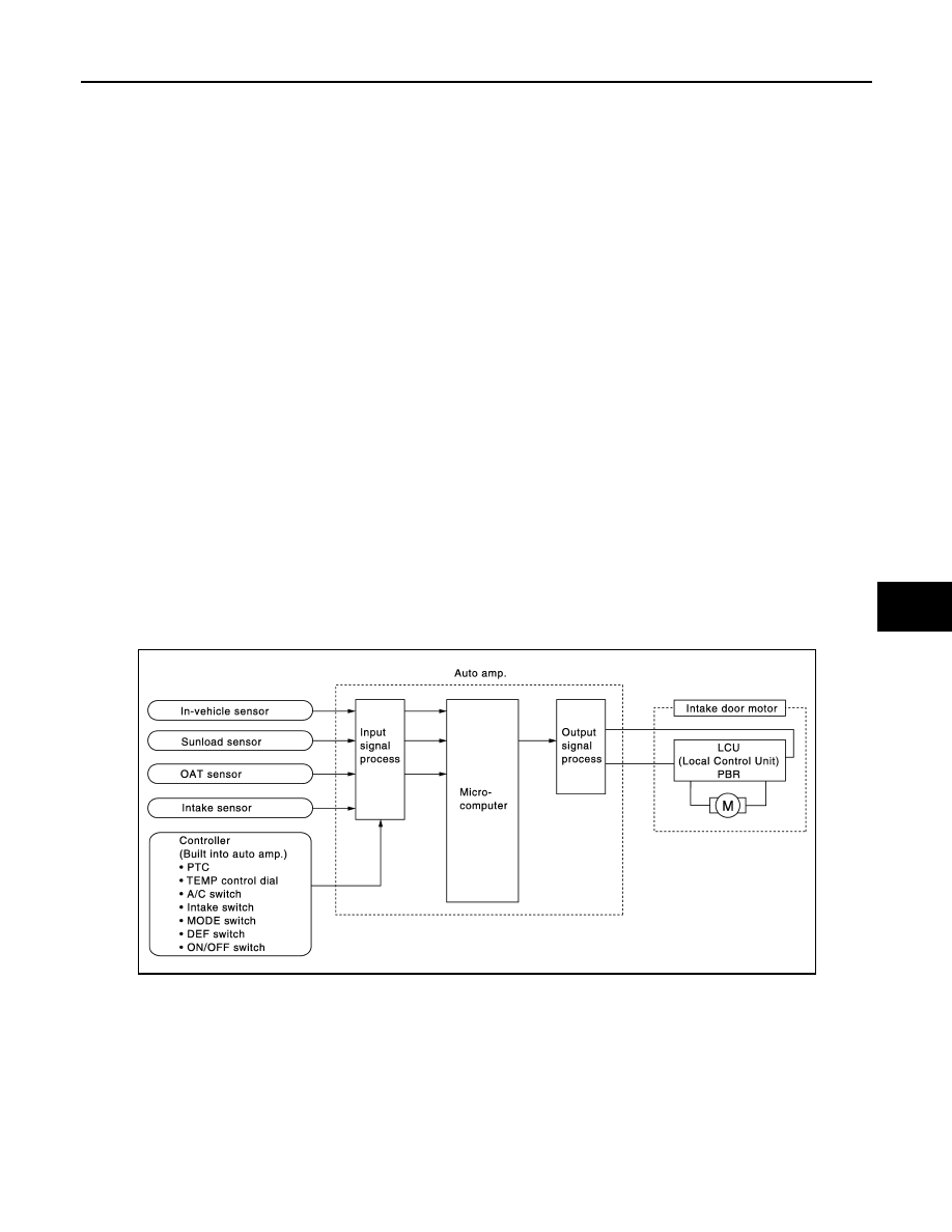
Description
INFOID:0000000000954640
SYSTEM DESCRIPTION
Component Parts
Intake door control system components are:
• Auto amp.
• Intake door motor (LCU)
• A/C LAN system (PBR built-in mode door motor, high-level ventilator door motor, air mix door motor and
intake door motor)
• In-vehicle sensor
• OAT sensor
• Sunload sensor
• Intake sensor
System Operation
• The auto amp. receives data from each of the sensors.
• The auto amp. sends air mix doors, mode door, high-level ventilator door and intake door opening angle
data to the air mix door motor LCUs, mode door motor LCU, high-level ventilator door motor LCU and intake
door motor LCU.
• The air mix door motors, mode door motor, high-level ventilator door motor and intake door motor read their
respective signals according to the address signal. Opening angle indication signals received from the auto
amp. and each of the motor position sensors are compared by the LCUs in each door motor with the existing
decision and opening angles.
• Subsequently, HOT/COLD, DEF/VENT, OPEN/SHUT and FRE/REC operation is selected. The new selec-
tion data are returned to the auto amp.
• The intake door control determines intake door position based on the ambient temperature, the intake air
temperature and the in-vehicle temperature. When shifting mode position D/F, when the DEF or OFF
switches are pressed, or when A/C switch is OFF, the auto amp. sets the intake door at the FRE position.
JPIIA0166GB
HAC-42
< FUNCTION DIAGNOSIS >
[AUTOMATIC AIR CONDITIONER]
INTAKE DOOR CONTROL SYSTEM
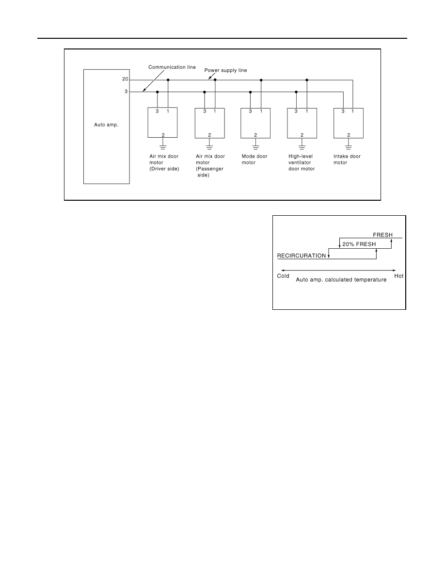
LAN System Circuit
Intake Door Control Specification
Intake door position is basically fixed at FRE when FRE indicator
lamps of DEF switch and intake switch turn ON, and fixed at REC
when REC indicator lamp of intake switch turns ON.
Intake door automatic control selects FRE, 20%FRE, or REC
depending on a target air mix door opening angle, based on in-vehi-
cle temperature, ambient temperature, and sunload.
JPIIA0122GB
RHA383H
BLOWER MOTOR CONTROL SYSTEM
HAC-43
< FUNCTION DIAGNOSIS >
[AUTOMATIC AIR CONDITIONER]
C
D
E
F
G
H
J
K
L
M
A
B
HAC
N
O
P
BLOWER MOTOR CONTROL SYSTEM
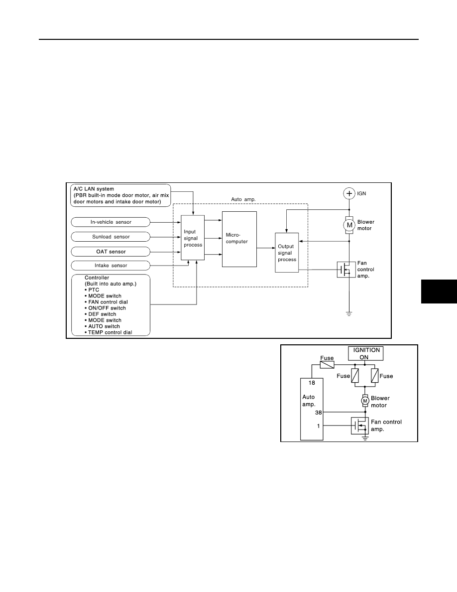
Description
INFOID:0000000000954641
SYSTEM DESCRIPTION
Component Parts
Fan speed control system components are:
• Auto amp.
• A/C LAN system (PBR built-in mode door motor, air mix door motors and intake door motor)
• In-vehicle sensor
• OAT sensor
• Sunload sensor
• Intake sensor
System Operation
Blower motor circuit
Automatic Mode
In the automatic mode, the blower motor speed is calculated by the auto amp. based on the input from the
PBR, in-vehicle sensor, sunload sensor, intake sensor and OAT sensor.
The blower motor applied voltage ranges from approximately 4 V (lowest speed) to 12 V (highest speed).
The control blower speed (in the range of 4 to 12 V), auto amp. supplies a gate voltage to the fan control amp.
Based on this voltage, fan control amp. control voltage supplied to the blower motor.
Starting Fan Speed Control
Start up from COLD SOAK Condition (Automatic mode)
In a cold start up condition where the engine coolant temperature is below 56
°
C (133
°
F), the blower will not
operate for a short period of time (up to 150 seconds). The exact start delay time varies depending on the
ambient and engine coolant temperature.
JPIIA0167GB
JPIIA0168GB
Нет комментариевНе стесняйтесь поделиться с нами вашим ценным мнением.
Текст