Nissan Qashqai (2007-2010). Manual — part 15
EM-8
< PRECAUTION >
[HR16DE]
PRECAUTIONS
PRECAUTION
PRECAUTIONS
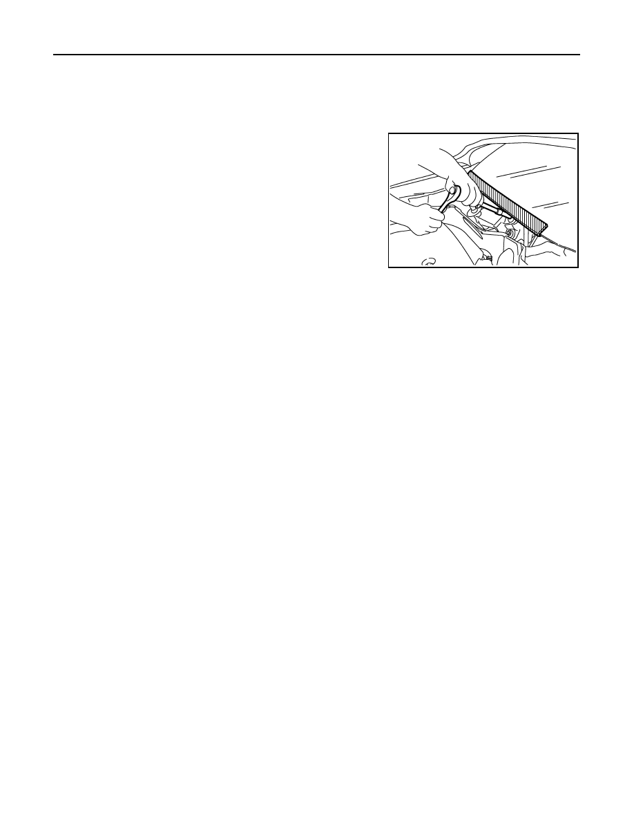
Precaution for Procedure without Cowl Top Cover
INFOID:0000000001117285
When performing the procedure after removing cowl top cover, cover
the lower end of windshield with urethane, etc.
Precaution Necessary for Steering Wheel Rotation After Battery Disconnect
INFOID:0000000001117286
NOTE:
• This Procedure is applied only to models with Intelligent Key system and NATS (NISSAN ANTI-THEFT SYS-
TEM).
• Remove and install all control units after disconnecting both battery cables with the ignition knob in the
″
LOCK
″
position.
• Always use CONSULT-III to perform self-diagnosis as a part of each function inspection after finishing work.
If DTC is detected, perform trouble diagnosis according to self-diagnostic results.
For models equipped with the Intelligent Key system and NATS, an electrically controlled steering lock mech-
anism is adopted on the key cylinder.
For this reason, if the battery is disconnected or if the battery is discharged, the steering wheel will lock and
steering wheel rotation will become impossible.
If steering wheel rotation is required when battery power is interrupted, follow the procedure below before
starting the repair operation.
OPERATION PROCEDURE
1.
Connect both battery cables.
NOTE:
Supply power using jumper cables if battery is discharged.
2.
Use the Intelligent Key or mechanical key to turn the ignition switch to the
″
ACC
″
position. At this time, the
steering lock will be released.
3.
Disconnect both battery cables. The steering lock will remain released and the steering wheel can be
rotated.
4.
Perform the necessary repair operation.
5.
When the repair work is completed, return the ignition switch to the
″
LOCK
″
position before connecting
the battery cables. (At this time, the steering lock mechanism will engage.)
6.
Perform a self-diagnosis check of all control units using CONSULT-III.
Draining Engine Coolant
INFOID:0000000000893815
Drain engine coolant and engine oil when the engine is cooled.
Disconnecting Fuel Piping
INFOID:0000000000893816
• Before starting work, make sure no fire or spark producing items are in the work area.
• Release fuel pressure before disconnecting and disassembly.
• After disconnecting pipes, plug openings to stop fuel leakage.
Removal and Disassembly
INFOID:0000000000893817
PIIB3706J
PRECAUTIONS
EM-9
< PRECAUTION >
[HR16DE]
C
D
E
F
G
H
I
J
K
L
M
A
EM
N
P
O
• When instructed to use SST, use specified tools. Always be careful to work safely, avoid forceful or unin-
structed operations.
• Exercise maximum care to avoid damage to mating or sliding surfaces.
• Dowel pins are used for several parts alignment. When replacing and reassembling parts with dowel pins,
make sure that dowel pins are installed in the original position.
• Cover openings of engine system with a tape or equivalent, if necessary, to seal out foreign materials.
• Mark and arrange disassembly parts in an organized way for easy troubleshooting and re-assembly.
• When loosening nuts and bolts, as a basic rule, start with the one furthest outside, then the one diagonally
opposite, and so on. If the order of loosening is specified, do exactly as specified. Power tools may be used
in the step.
Inspection, Repair and Replacement
INFOID:0000000000893818
Before repairing or replacing, thoroughly inspect parts. Inspect new replacement parts in the same way, and
replace if necessary.
Assembly and Installation
INFOID:0000000000893819
• Use torque wrench to tighten bolts or nuts to specification.
• When tightening nuts and bolts, as a basic rule, equally tighten in several different steps starting with the
ones in center, then ones on inside and outside diagonally in this order. If the order of tightening is specified,
do exactly as specified.
• Replace with new gasket, packing, oil seal or O-ring.
• Thoroughly wash, clean, and air-blow each part. Carefully check engine oil or engine coolant passages for
any restriction and blockage.
• Avoid damaging sliding or mating surfaces. Completely remove foreign materials such as cloth lint or dust.
Before assembly, oil sliding surfaces well.
• Release air within route when refilling after draining engine coolant.
• After repairing, start the engine and increase engine speed to check engine coolant, fuel, engine oil, and
exhaust gases for leakage.
Parts Requiring Angle Tightening
INFOID:0000000000893820
• Use the angle wrench [SST: KV10112100] for the final tightening of the following engine parts:
- Cylinder head bolts
- Main bearing cap bolts
- Connecting rod cap bolts
- Crankshaft pulley bolt (No the angle wrench is required as bolt flange is provided with notches for angle
tightening)
• Never use a torque value for final tightening.
• The torque value for these parts are for a preliminary step.
• Ensure thread and seat surfaces are clean and coated with engine oil.
Liquid Gasket
INFOID:0000000000893821
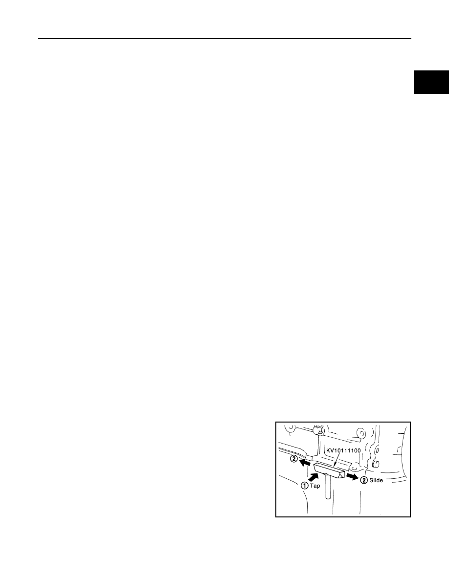
REMOVAL OF LIQUID GASKET
• After removing the mounting bolts and nuts, separate the mating
surface using seal cutter (SST) and remove the old liquid gasket
sealing.
CAUTION:
Be careful not to damage the mating surfaces.
• Tap seal cutter to insert it (1), and then slide it (2) by tapping on the
side as shown in the figure.
• In areas where seal cutter is difficult to use, use plastic hammer to
lightly tap the parts, to remove it.
CAUTION:
If for some unavoidable reason tool such as screwdriver is
used, be careful not to damage the mating surfaces.
LIQUID GASKET APPLICATION PROCEDURE
PBIC0275E
EM-10
< PRECAUTION >
[HR16DE]
PRECAUTIONS
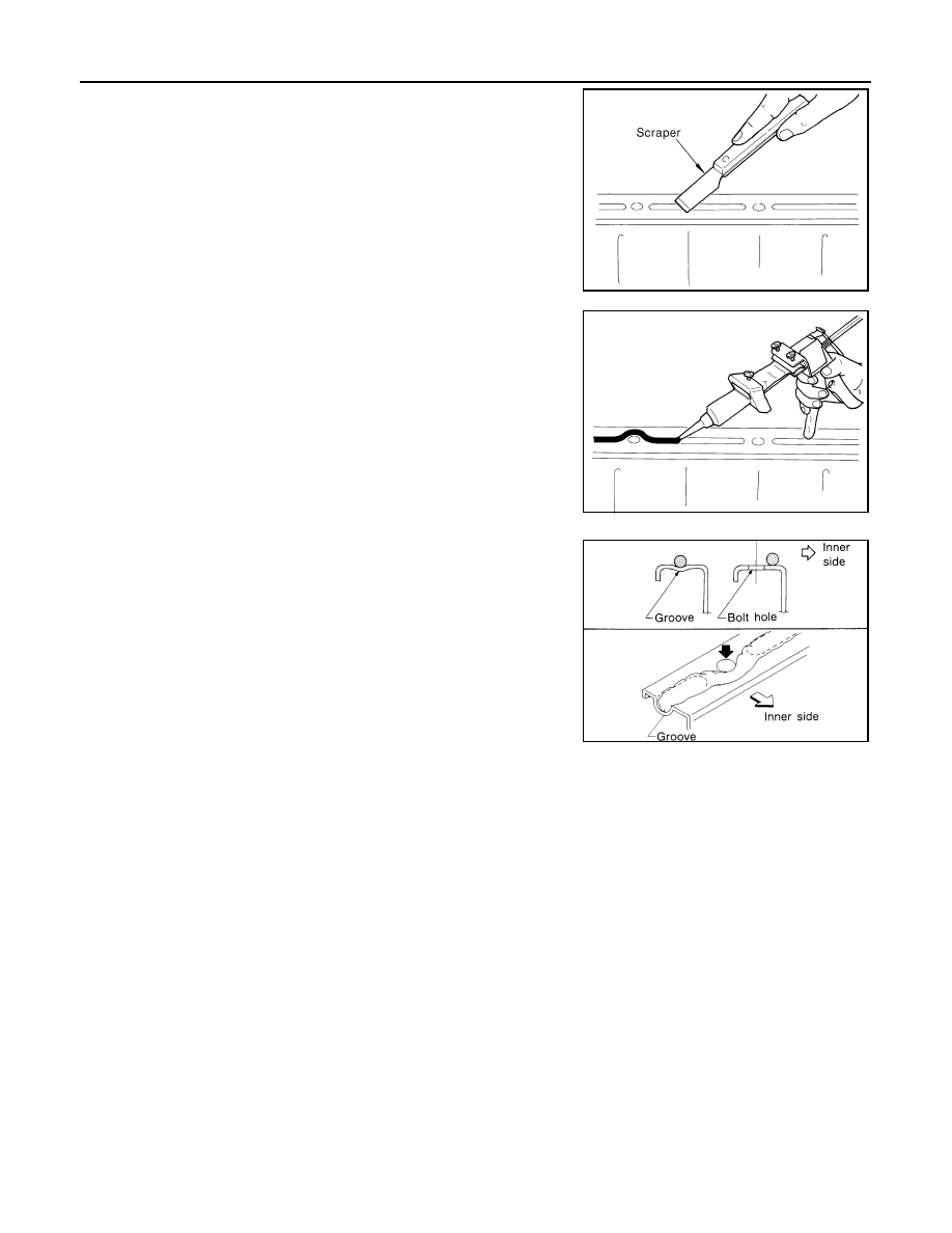
1.
Using a scraper, remove the old liquid gasket adhering to the liq-
uid gasket application surface and the mating surface.
• Remove the liquid gasket completely from the groove of the
liquid gasket application surface, mounting bolts and bolt
holes.
2.
Wipe the liquid gasket application surface and the mating sur-
face with white gasoline (lighting and heating use) to remove
adhering moisture, grease and foreign materials.
3.
Attach liquid gasket tube to the tube presser (commercial ser-
vice tool).
Use Genuine Liquid Gasket or equivalent.
4.
Apply the liquid gasket without breaks to the specified location
with the specified dimensions.
• If there is a groove for the liquid gasket application, apply the
liquid gasket to the groove.
• As for the bolt holes, normally apply the liquid gasket inside
the holes. Occasionally, it should be applied outside the holes.
Make sure to read the text of service manual.
• Within 5 minutes of liquid gasket application, install the mating
component.
• If the liquid gasket protrudes, wipe it off immediately.
• Do not retighten mounting bolts or nut after the installation.
• Wait 30 minutes or more after installation before refilling
engine oil and engine coolant.
CAUTION:
If there are specific manuals in this instruction, observe
them.
PBIC0003E
EMA0622D
SEM159F
PREPARATION
EM-11
< PREPARATION >
[HR16DE]
C
D
E
F
G
H
I
J
K
L
M
A
EM
N
P
O
PREPARATION
PREPARATION
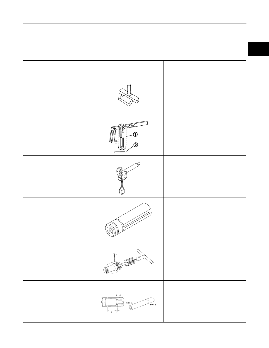
Special Service Tools
INFOID:0000000000893822
Tool number
Tool name
Description
KV10111100
Seal cutter
Removing oil pan (lower and upper) etc.
KV10116200
Valve spring compressor
1. KV10115900
Attachment
2. KV10109220
Adapter
Disassembling and assembling valve mecha-
nism
Part (1) is a component of KV10116200, but
Part (2) is not so.
KV10112100
Angle wrench
Tightening bolts for bearing cap, cylinder
head, etc. in angle
KV10117100
Heated oxygen sensor wrench
Loosening or tightening heated oxygen sen-
sor 1
For 22 mm (0.87 in) width hexagon nut
KV10107902
Valve oil seal puller
1. KV10116100
Valve oil seal puller adapter
Removing valve oil seal
KV10115600
Valve oil seal drift
Installing valve oil seal
Use side A.
a: 20 (0.79) dia. d: 8 (0.31) dia.
b: 13 (0.51) dia. e: 10.7 (0.421)
c: 10.3 (0.406) dia. f: 5 (0.20)
Unit: mm (in)
S-NT046
PBIC1650E
S-NT014
NT379
SZNT605
S-NT603
Нет комментариевНе стесняйтесь поделиться с нами вашим ценным мнением.
Текст