Nissan Qashqai (2007-2010). Manual — part 1246
SEC-184
< COMPONENT DIAGNOSIS >
[WITHOUT INTELLIGENT KEY SYSTEM]
POWER SUPPLY AND GROUND CIRCUIT
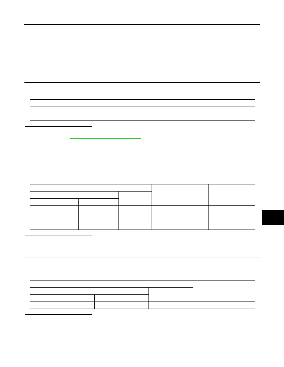
Does continuity exist?
YES
>> INSPECTION END
NO
>> Repair harness or connector.
KEY SWITCH
SEC-185
< COMPONENT DIAGNOSIS >
[WITHOUT INTELLIGENT KEY SYSTEM]
C
D
E
F
G
H
I
J
L
M
A
B
SEC
N
O
P
KEY SWITCH
Description
INFOID:0000000001097819
Key switch detects that ignition key is inserted into the key cylinder, and then transmits the signal to BCM.
Component Function Check
INFOID:0000000001097820
1.
CHECK KEY SWITCH INPUT SIGNAL
Check key switch (“KEY SW”) in “DATA MONITOR” mode with CONSULT-III. Refer to
: CONSULT-III Function (BCM - DOOR LOCK)"
.
Is the inspection result normal?
YES
>> Key switch is OK.
NO
>> Refer to
SEC-185, "Diagnosis Procedure"
Diagnosis Procedure
INFOID:0000000001097821
1.
CHECK KEY SWITCH INPUT SIGNAL
1.
Turn ignition switch OFF.
2.
Disconnect BCM connector.
3.
Check voltage between BCM harness connector and ground.
Is the inspection result normal?
YES
>> Check intermittent incident. Refer to
GI-39, "Intermittent Incident"
.
NO
>> GO TO 2.
2.
CHECK KEY SWITCH POWER SUPPLY CIRCUIT
1.
Remove ignition key from key cylinder.
2.
Disconnect key switch connector.
3.
Check voltage between key switch harness connector and ground.
Is the inspection result normal?
YES
>> GO TO 3.
NO
>> Repair or replace harness.
3.
CHECK KEY SWITCH SIGNAL CIRCUIT
1.
Check continuity between BCM harness connector and key switch connector.
Monitor item
Condition
KEY SW
Insert mechanical key into key cylinder
: ON
Remove mechanical key from key cylinder
: OFF
Terminals
Condition
Voltage (V)
(Approx.)
(+)
(–)
BCM connector
Terminal
M65
36
Ground
Insert ignition key into key cyl-
inder
Battery voltage
Remove ignition key from key
cylinder
0
Terminals
Voltage (V)
(Approx.)
(+)
(–)
Key switch connector
Terminal
M25
2
Ground
Battery voltage

SEC-186
< COMPONENT DIAGNOSIS >
[WITHOUT INTELLIGENT KEY SYSTEM]
KEY SWITCH
2.
Check continuity between key switch connector and ground.
Is the inspection result normal?
YES
>> GO TO 4.
NO
>> Repair or replace harness.
4.
CHECK KEY SWITCH
Check key switch function.
Refer to
SEC-186, "Component Inspection"
.
Is the inspection result normal?
YES
>> Check intermittent incident. Refer to
GI-39, "Intermittent Incident"
.
NO
>> Replace key switch.
Component Inspection
INFOID:0000000001097822
COMPONENT INSPECTION
1.
CHECK KEY SWITCH
Check continuity between key switch terminals.
Is the inspection result normal?
YES
>> Key switch is OK.
NO
>> Replace key switch.
BCM connector
Terminal
Key switch connector
Terminal
Continuity
M65
36
M25
1
Existed
Key switch connector
Terminal
Ground
Continuity
M25
1
Ground
Not existed
Terminal
Condition
Continuity
key switch connector
1
2
Insert ignition key into key cylinder
Existed
Remove ignition key from key cylinder
Not existed

STOP LAMP
SEC-187
< COMPONENT DIAGNOSIS >
[WITHOUT INTELLIGENT KEY SYSTEM]
C
D
E
F
G
H
I
J
L
M
A
B
SEC
N
O
P
STOP LAMP
Description
INFOID:0000000001157664
Stop lamp switch detects that brake pedal is depressed, and then transmits the signal to BCM.
Component Function Check
INFOID:0000000001157665
1.
CHECK STOP LAMP SWITCH INPUT SIGNAL
Check stop lamp function by depressing brake pedal.
Is the inspection result normal?
YES
>> Stop lamp switch is OK.
NO
>> Refer to
Diagnosis Procedure
INFOID:0000000001157666
1.
CHECK STOP LAMP SWITCH INPUT SIGNAL
1.
Turn ignition switch OFF.
2.
Disconnect BCM connector.
3.
Check voltage between BCM harness connector and ground.
Is the inspection result normal?
YES
>> Check intermittent incident. Refer to
GI-39, "Intermittent Incident"
.
NO
>> GO TO 2.
2.
CHECK STOP LAMP SWITCH POWER SUPPLY CIRCUIT
1.
Disconnect stop lamp switch connector.
2.
Check voltage between stop lamp switch harness connector and ground.
Is the inspection result normal?
YES
>> GO TO 3.
NO
>> Repair or replace harness.
3.
CHECK STOP LAMP SWITCH SIGNAL CIRCUIT
1.
Check continuity between BCM harness connector and stop lamp switch connector.
2.
Check continuity between stop lamp switch connector and ground.
Terminals
Condition
Voltage (V)
(Approx.)
(+)
(–)
BCM connector
Terminal
M66
51
Ground
Brake pedal is depressed
Battery voltage
Brake pedal is not depressed
0
Terminals
Voltage (V)
(Approx.)
(+)
(–)
Stop lamp switch connector
Terminal
E114 (with gasoline engine and M/
T models)
E115 (except gasoline engine and
M/T models)
1
Ground
Battery voltage
BCM connector
Terminal
Stop lamp switch connector
Terminal
Continuity
M66
51
E114 (with gasoline engine
and M/T models)
E115 (except gasoline en-
gine and M/T models)
2
Existed
Нет комментариевНе стесняйтесь поделиться с нами вашим ценным мнением.
Текст