Nissan Qashqai (2007-2010). Manual — part 658

FAX-54
< ON-VEHICLE REPAIR >
[4WD]
FRONT DRIVE SHAFT BOOT
29. Install transverse to steering knuckle. Refer to
.
30. Install steering outer socket to steering knuckle. Refer to
.
31. Install disc rotor.
32. Install torque member to steering knuckle. Refer to
BR-37, "BRAKE CALIPER ASSEMBLY : Exploded
BR-81, "BRAKE CALIPER ASSEMBLY : Exploded View"
33. Install lock plate to strut assembly. Refer to
BR-19, "FRONT BRAKE (WITH ABS) : Exploded View"
with ABS),
BR-21, "FRONT BRAKE (WITH ESP) : Exploded View"
(LHD with ESP),
BRAKE (WITH ABS) : Exploded View"
(RHD with ABS),
BR-65, "FRONT BRAKE (WITH ESP) : Exploded
(RHD with ESP).
34. Install wheel sensor to steering knuckle. Refer to
BRC-67, "FRONT WHEEL SENSOR : Exploded View"
(with ABS),
BRC-172, "FRONT WHEEL SENSOR : Exploded View"
35. Tighten the hub lock nut to the specified torque. Refer to
36. Install cotter pin.
CAUTION:
• Never reuse cotter pin.
• Bend cotter pin at the root sufficiently to prevent any looseness.
37. Install tires to vehicle.
FRONT DRIVE SHAFT
FAX-55
< ON-VEHICLE REPAIR >
[4WD]
C
E
F
G
H
I
J
K
L
M
A
B
FAX
N
O
P
FRONT DRIVE SHAFT
Exploded View
INFOID:0000000001080625
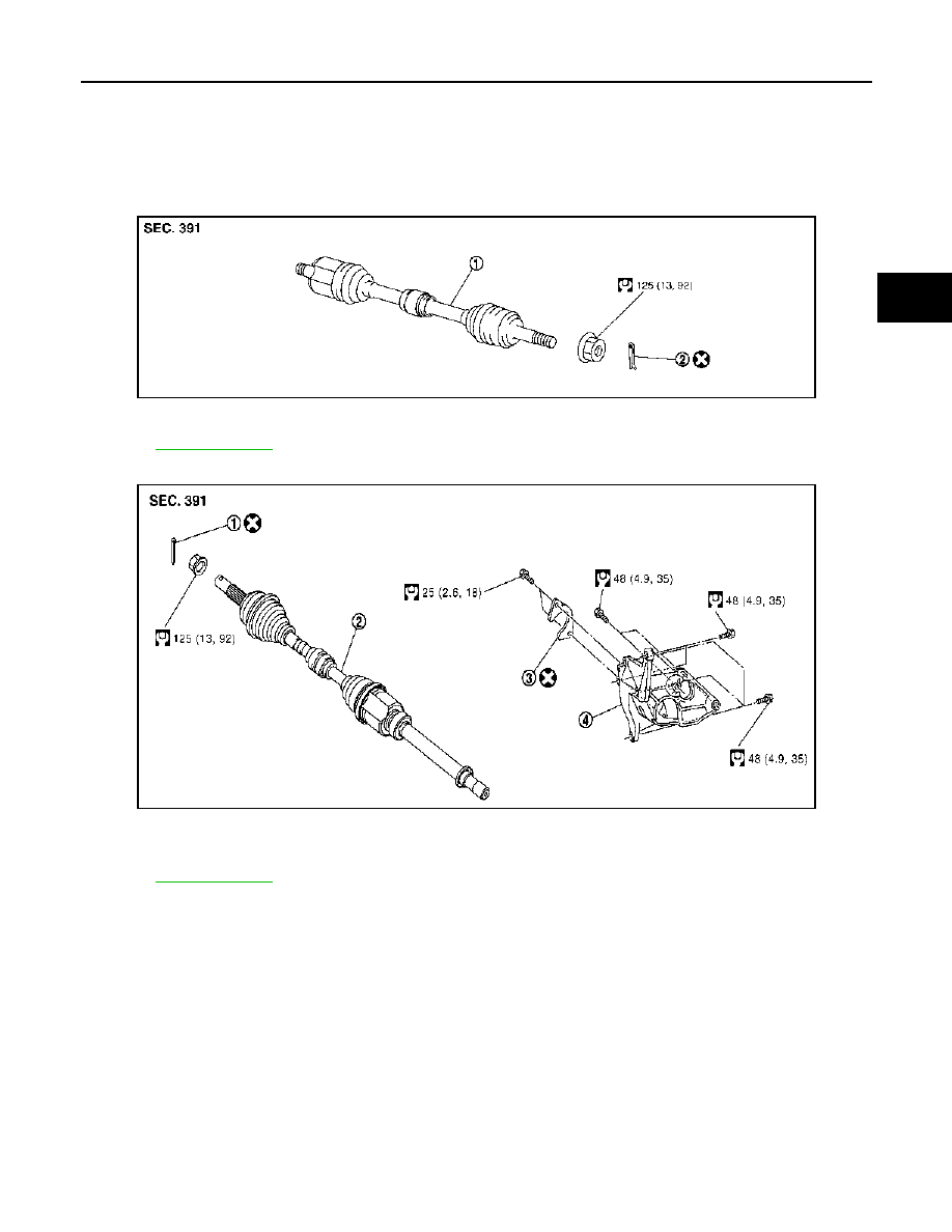
REMOVAL
Left side
Right side
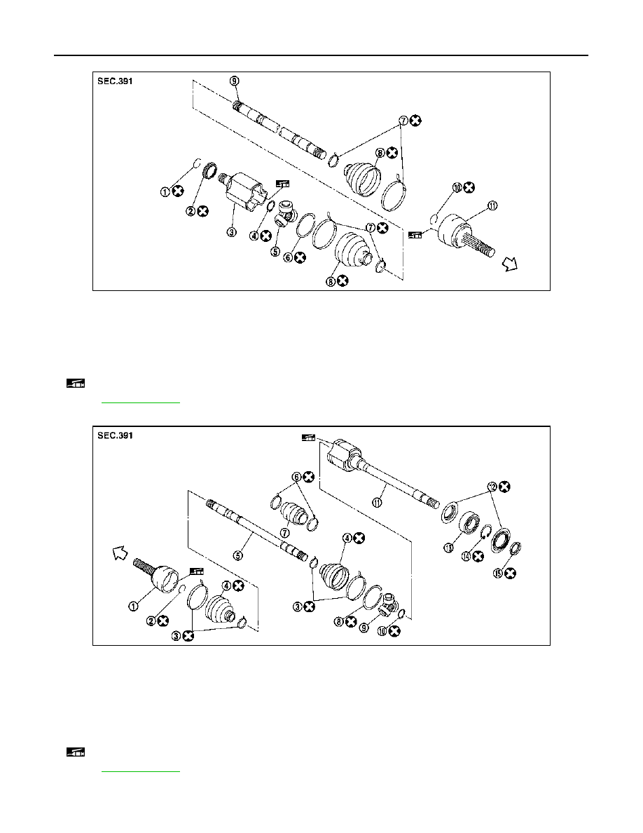
DISASSEMBLY
PDIA1192J
1.
Drive shaft
2.
Cotter pin
Refer to
JPDIF0041GB
1.
Cotter pin
2.
Drive shaft
3.
Plate
4.
Support bearing bracket
Refer to
symbols in the figure.
FAX-56
< ON-VEHICLE REPAIR >
[4WD]
FRONT DRIVE SHAFT
Left side
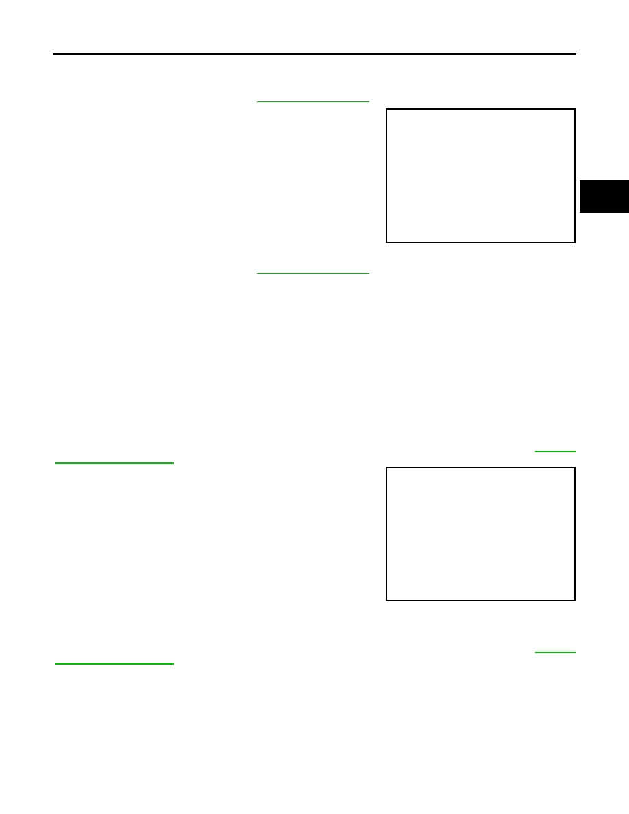
Right side
Removal and Installation
INFOID:0000000001080679
JPDIF0046ZZ
1.
Circular clip
2.
Dust shield
3.
Housing
4.
Snap ring
5.
Spider assembly
6.
Stopper ring
7.
Boot band
8.
Boot
9.
Shaft
10. Circular clip
11. Joint sub-assembly
: Wheel side
: Fill NISSAN Genuine grease or equivalent.
Refer to
for symbols not described on the above.
JPDIF0045ZZ
1.
Joint sub-assembly
2.
Circular clip
3.
Boot band
4.
Boot
5.
Shaft
6.
Damper band
7.
Dynamic damper
8.
Stopper ring
9.
Spider assembly
10. Snap ring
11. Housing
12. Dust shield
13. Support bearing
14. Snap ring
15. Dust shield
: Wheel side
: Fill NISSAN Genuine grease or equivalent.
Refer to
for symbols not described on the above.
FRONT DRIVE SHAFT
FAX-57
< ON-VEHICLE REPAIR >
[4WD]
C
E
F
G
H
I
J
K
L
M
A
B
FAX
N
O
P
REMOVAL
Left Side
1.
Refer to the procedure from 1 to 11 in
2.
Remove drive shaft from transaxle assembly.
• Use the drive shaft attachment (A) (SST:KV40107500) and a
sliding hammer (B) while inserting tip of the drive shaft attach-
ment between housing and transaxle assembly.
CAUTION:
Never place drive shaft joint at an extreme angle when
removing drive shaft. Also be careful not to overextend
slide joint.
Right Side
1.
Refer to the procedure from 1 to 11 in
2.
Remove plate bolts and plate.
3.
If necessary, remove the support bearing bracket bolts and the support bearing bracket.
4.
Remove drive shaft from transaxle assembly.
• Use the drive shaft attachment (SST:KV40107500) and a sliding hammer while inserting tip of the drive
shaft attachment between housing and transaxle assembly.
CAUTION:
Never place drive shaft joint at an extreme angle when removing drive shaft. Also be careful not
to overextend slide joint.
INSTALLATION
Left Side
Note the following, and install in the reverse order of removal.
CAUTION:
Always replace differential side oil seal with new one when installing drive shaft. Refer to
(CVT).
• Place the protector (A) (SST:KV38107900) onto transaxle assem-
bly to prevent damage to the oil seal while inserting drive shaft.
Slide drive shaft sliding joint and tap with a hammer to install
securely.
CAUTION:
Make sure that circular clip is completely engaged.
Right Side
Note the following, and install in the reverse order of removal.
CAUTION:
Always replace differential side oil seal with new one when installing drive shaft. Refer to
(CVT).
JPDIF0004ZZ
JPDIF0023ZZ
Нет комментариевНе стесняйтесь поделиться с нами вашим ценным мнением.
Текст