Nissan Qashqai (2007-2010). Manual — part 1965

AV-118
< COMPONENT DIAGNOSIS >
[AUDIO WITH NAVIGATION]
STEERING SWITCH SIGNAL GND CIRCUIT
STEERING SWITCH SIGNAL GND CIRCUIT
Description
INFOID:0000000000955227
Transmits the steering switch signal to audio unit.
Diagnosis Procedure
INFOID:0000000000947127
1.
CHECK STEERING SWITCH SIGNAL GND CIRCUIT
1.
Disconnect audio unit connector and spiral cable connector.
2.
Check continuity between audio unit harness connector terminal 15 and spiral cable harness connector
terminal 31.
3.
Connect audio unit connector.
Is inspection result OK?
YES
>> GO TO 2.
NO
>> Repair harness or connector.
2.
CHECK SPIRAL CABLE
Check spiral cable.
Is inspection result OK?
YES
>> GO TO 3.
NO
>> Replace spiral cable.
3.
CHECK GROUND CIRCUIT
1.
Connect audio unit connector.
2.
Check continuity between audio unit harness connector terminal 15 and ground.
Is inspection result OK?
YES
>> GO TO 4.
NO
>> Replace audio unit.
4.
CHECK STEERING SWITCH
1.
Turn ignition switch OFF.
2.
Check steering switch. Refer to
AV-118, "Component Inspection"
Is inspection result OK?
YES
>> INSPECTION END
NO
>> Replace steering switch.
Component Inspection
INFOID:0000000000955228
Measure the resistance between the steering switch connector terminals 20 to 17 and 16 to 17.
Standard
15 - 31
: Continuity should exist.
15 - Ground
: Continuity should exist.
Between terminals 20 and
17
ENTER switch ON
: 990 – 1030
Ω
MENU DOWN switch ON
: 324 – 336
Ω
MENU UP switch ON
: 108 – 112
Ω
SOURCE switch ON
: 0
Ω
Between terminals 16 and
17
JPNIA0166GB

AV
STEERING SWITCH SIGNAL GND CIRCUIT
AV-119
< COMPONENT DIAGNOSIS >
[AUDIO WITH NAVIGATION]
C
D
E
F
G
H
I
J
K
L
M
B
A
O
P
switch ON
: 990 – 1030
Ω
switch ON
: 324 – 336
Ω
VOL UP switch ON
: 108 – 112
Ω
VOL DOWN switch ON
: 0
Ω

AV-120
< ECU DIAGNOSIS >
[AUDIO WITH NAVIGATION]
NAVI CONTROL UNIT
ECU DIAGNOSIS
NAVI CONTROL UNIT
Reference Value
INFOID:0000000000947129
VALUES ON THE DIAGNOSIS TOOL
CONSULT-III data monitor item
TERMINAL LAYOUT
PHYSICAL VALUES
Display Item
Dis-
play
Vehicle status
Remarks
VHCL SPD SIG
ON
Vehicle speed >0 km/h (0 MPH)
Changes in indication may be delayed. This is
normal.
OFF
Vehicle speed =0 km/h (0 MPH)
PKB SIG
ON
Parking brake is applied.
Changes in indication may be delayed. This is
normal.
OFF
Parking brake is released.
ILLUM SIG
ON
Lighting switch ON
—
OFF
Lighting switch OFF
IGN SIG
ON
Ignition switch ON
—
OFF
Ignition switch in ACC position
REV SIG
ON
Selector lever in R position
Changes in indication may be delayed. This is
normal.
OFF
Selector lever in any position other
than R
JPNIA0226ZZ
Terminal
(Wire color)
Description
Condition
Reference value
(Approx.)
+
–
Signal name
Input/
Output
1
(B)
Ground
GND
—
Ignition
switch
ON
—
0 V
2
(LG)
Ground
Battery power supply
Input
Ignition
switch
OFF
—
Battery voltage
5
(R)
Ground
ACC power supply
Input
Ignition
switch
ACC
—
Battery voltage
6
(B)
7
Microphone VCC
Output
Ignition
switch
ON
—
5 V
7
Ground
Microphone GND
—
Ignition
switch
ON
—
0 V
AV
NAVI CONTROL UNIT
AV-121
< ECU DIAGNOSIS >
[AUDIO WITH NAVIGATION]
C
D
E
F
G
H
I
J
K
L
M
B
A
O
P
8
(W)
7
Microphone signal
Input
Ignition
switch
ON
Sounds
9
—
Shield
—
—
—
—
10
(W)
11
(O)
TEL voice signal
Output
Ignition
switch
ON
TEL voice output
12
(O)
14
(W)
Voice guidance signal
Output
Ignition
switch
ON
Voice guidance output
13
—
Shield
—
—
—
—
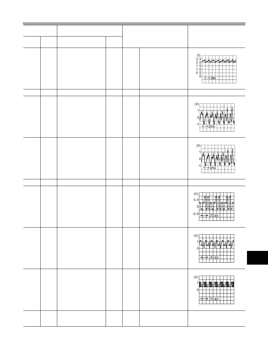
44
(G)
47
(B)
RGB signal (R: red)
Output
Ignition
switch
ON
Start “Confirmation / Adjust-
ment Mode”, and then dis-
play color bar by selecting
“Color Spectrum Bar” on
DISPLAY DIAGNOSIS
screen.
45
(R)
47
(B)
RGB signal (G: green)
Output
Ignition
switch
ON
Start “Confirmation / Adjust-
ment Mode”, and then dis-
play color bar by
selecting“Color Spectrum
Bar” on DISPLAY DIAGNO-
SIS screen.
46
(W)
47
(B)
RGB signal (B: blue)
Output
Ignition
switch
ON
Start “Confirmation / Adjust-
ment Mode”, and then dis-
play color bar by
selecting“Color Spectrum
Bar” on DISPLAY DIAGNO-
SIS screen.
47
(B)
Ground
RGB ground
—
Ignition
switch
ON
—
0 V
Terminal
(Wire color)
Description
Condition
Reference value
(Approx.)
+
–
Signal name
Input/
Output
PKIB5037J
SKIB3609E
SKIB3609E
JPNIA0221ZZ
JPNIA0222ZZ
JPNIA0223ZZ
Нет комментариевНе стесняйтесь поделиться с нами вашим ценным мнением.
Текст