Nissan Qashqai (2007-2010). Manual — part 917
HAC-28
< FUNCTION DIAGNOSIS >
[AUTOMATIC AIR CONDITIONER]
DIAGNOSIS SYSTEM (AUTO AMP.)
1.
Turn ignition switch ON.
2.
Set in self-diagnosis mode as follows. Within 10 seconds after starting engine (ignition switch is turned
ON.), press ON/OFF switch for at least 5 seconds.
NOTE:
If battery voltage drops below 12 V during diagnosis STEP-3, door motor speed becomes slower and as a
result, the system may generate an error even when operation is normal. To avoid this, start engine before
performing this diagnosis.
>> GO TO 2.
2.
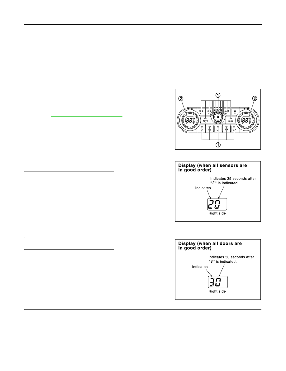
STEP-1: LEDS AND DISPLAY ARE CHECKED
Check LEDs (1) illumination and display screen (2).
Is this inspection result normal?
YES
>> GO TO 3.
NO
>> Malfunctioning ON/OFF switch or auto amp. Refer to
HAC-115, "Inspection procedure"
.
3.
STEP-2: SENSOR AND DOOR MOTOR CIRCUITS ARE CHECKED FOR OPEN OR SHORT CIRCUIT
Turn temperature control dial (driver side) clockwise.
Does code No. 20 appear on the display?
YES
>> GO TO 4.
NO
>> GO TO 11.
4.
STEP-3: MODE DOOR, HIGH-LEVEL VENTILATOR DOOR AND INTAKE DOOR POSITIONS ARE
CHECKED
Turn temperature control dial (driver side) clockwise.
Does code No. 30 appear on the display?
YES
>> GO TO 5.
NO
>> GO TO 12.
5.
STEP-4: OPERATION OF EACH DOOR MOTOR IS CHECKED
JPIIA0173ZZ
JPIIA0116GB
JPIIA0117GB
DIAGNOSIS SYSTEM (AUTO AMP.)
HAC-29
< FUNCTION DIAGNOSIS >
[AUTOMATIC AIR CONDITIONER]
C
D
E
F
G
H
J
K
L
M
A
B
HAC
N
O
P
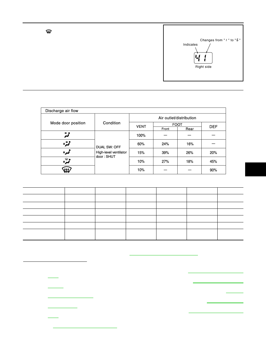
1.
Turn temperature control dial (driver side) clockwise.
2.
Press
(DEF) switch. Code No. of each door motor test is
indicated on the display.
>> GO TO 6.
6.
CHECK ACTUATORS
Refer to the following chart and check discharge air flow, air temperature, blower motor voltage and compres-
sor operation.
Checks must be made visually, by listening the sound, or by touching air outlets with hand, etc. for improper
operation.
*1: FOOT position during automatic control. Refer to
HAC-6, "Description & Inspection"
Is this inspection result normal?
YES
>> GO TO 7.
NO-1
>> Air outlet does not change. Go to Mode Door Motor Circuit. Refer to
.
NO-2
>> Intake door does not change. Go to Intake Door Motor Circuit. Refer to
NO-3
>> Discharge air temperature does not change. Go to Air Mix Door Motor Circuit. Refer to
.
NO-4
>> Blower motor operation is malfunctioning. Go to Blower Motor Circuit. Refer to
NO-5
>> Magnet clutch does not engage. Go to Magnet Clutch Circuit. Refer to
.
NO-6
>> High-level ventilator door does not change. Go to High-level Ventilator Door Motor Circuit. Refer
to
.
JPIIA0118GB
JPIIA0082GB
Code No.
41
42
43
44
45
46
Mode door position
VENT
B/L 1
B/L 2
FOOT
*1
D/F
DEF
Intake door position
REC
REC
20% FRE
FRE
FRE
FRE
Air mix door position
FULL COOL
FULL COOL
FULL HOT
FULL HOT
FULL HOT
FULL HOT
Blower motor voltage
5 V
11.75 V
8.5 V
8.5 V
8.5 V
11.75 V
Compressor
ON
ON
OFF
OFF
ON
ON
High-level ventilator
door position
OPEN
OPEN
OPEN
OPEN
SHUT
SHUT
HAC-30
< FUNCTION DIAGNOSIS >
[AUTOMATIC AIR CONDITIONER]
DIAGNOSIS SYSTEM (AUTO AMP.)
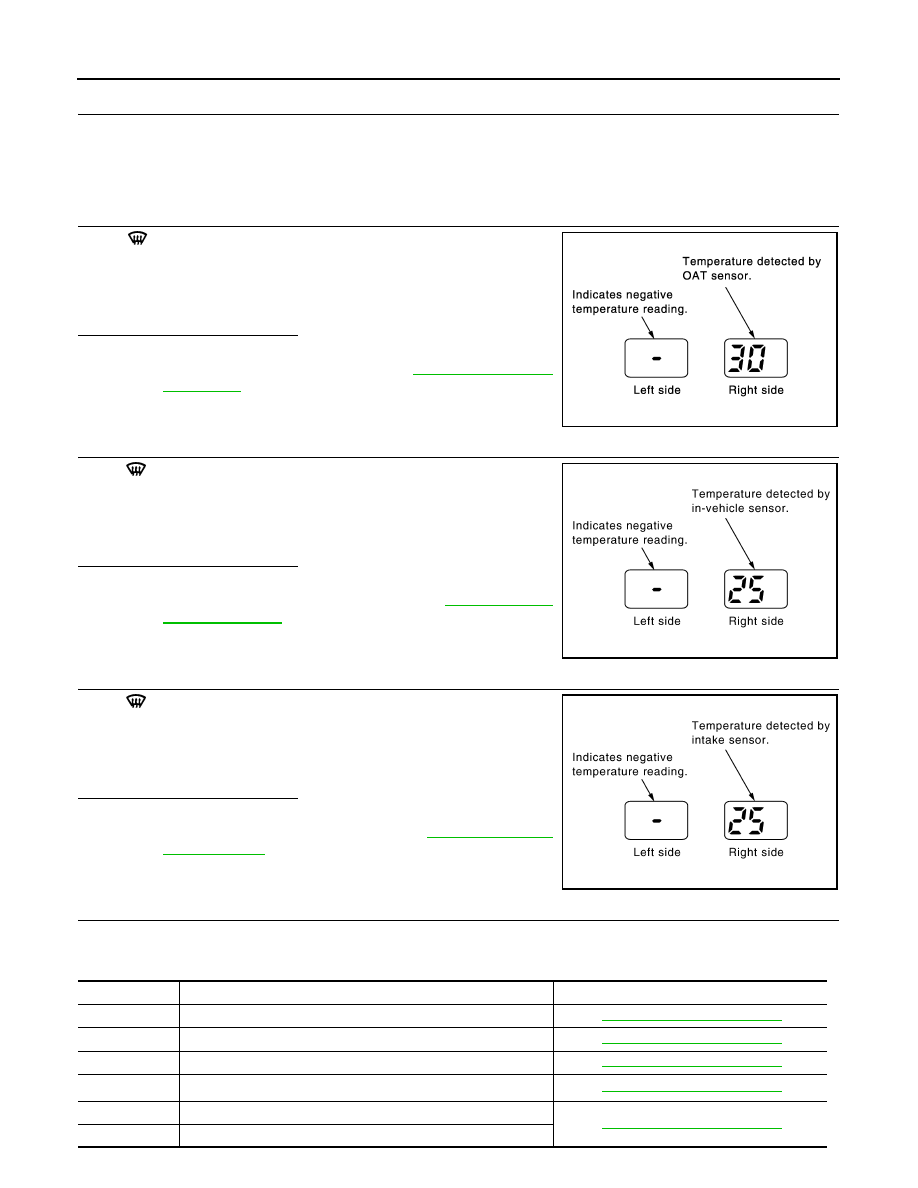
7.
STEP-5: TEMPERATURE OF EACH SENSOR IS CHECKED
1.
Turn temperature control dial (driver side) clockwise.
2.
Code No. 51 appears on the display.
>> GO TO 8.
8.
CHECK OAT SENSOR
Press
(DEF) switch one time. Temperature detected by OAT
sensor is indicated on the display.
NOTE:
If the temperature indicated on the display greatly differs from the
actual temperature, check sensor circuit first, and then check sensor.
Is this inspection result normal?
YES
>> GO TO 9.
NO
>> Go to OAT Sensor Circuit. Refer to
.
9.
CHECK IN-VEHICLE SENSOR
Press
(DEF) switch for the one time. Temperature detected by
in-vehicle sensor is indicated on the display.
NOTE:
If the temperature indicated on the display greatly differs from the
actual temperature, check sensor circuit first, and then check sensor.
Is this inspection result normal?
YES
>> GO TO 10.
NO
>> Go to In-vehicle Sensor Circuit. Refer to
.
10.
CHECK INTAKE SENSOR
Press
(DEF) switch for the one time. Temperature detected by
intake sensor is indicated on the display.
NOTE:
If the temperature indicated on the display greatly differs from the
actual temperature, check sensor circuit first, and then check sensor.
Is this inspection result normal?
YES
>> GO TO 11.
NO
>> Go to Intake Sensor Circuit. Refer to
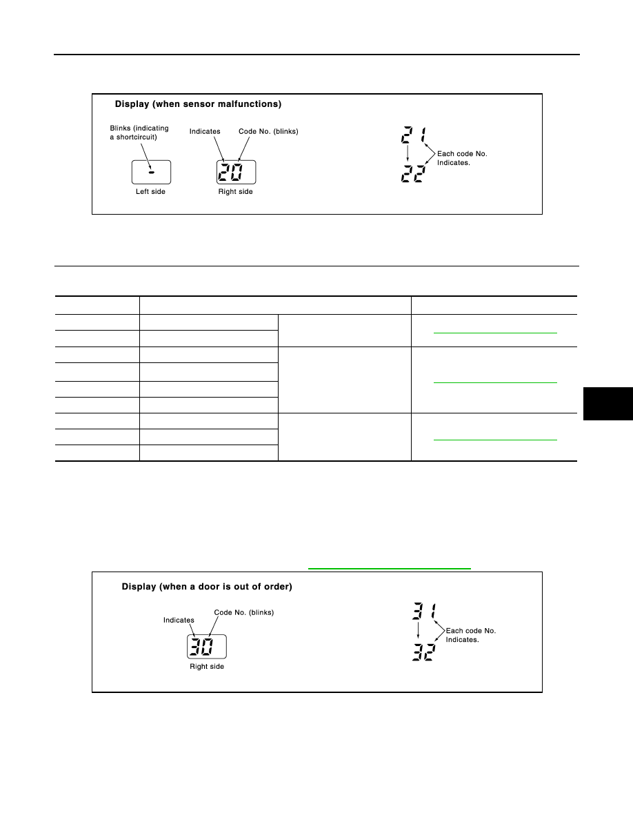
11.
CHECK MALFUNCTIONING SENSOR AND DOOR MOTOR
Refer to the following chart for malfunctioning code No.
(If two or more sensors and door motors malfunction, corresponding code Nos. indicates 1 second each.)
JPIIA0110GB
JPIIA0111GB
JPIIA0112GB
Code No.
Malfunctioning sensor and door motor (Including circuits)
Reference
21 /
−
21
OAT sensor
22 /
−
22
In-vehicle sensor
24 /
−
24
Intake sensor
25 /
−
25
Sunload sensor
*
26 /
−
26
Air mix door motor PBR (Driver side)
27 /
−
27
Air mix door motor PBR (Passenger side)
DIAGNOSIS SYSTEM (AUTO AMP.)
HAC-31
< FUNCTION DIAGNOSIS >
[AUTOMATIC AIR CONDITIONER]
C
D
E
F
G
H
J
K
L
M
A
B
HAC
N
O
P
*: Perform self-diagnosis STEP-2 under sunshine.
When performing indoors, aim a light (more than 60 W) at sunload sensor, otherwise code No. 25 will indicate
despite that sunload sensor is functioning properly.
>> INSPECTION END
12.
CHECK MALFUNCTIONING DOOR MOTOR POSITION SWITCH
Mode, high-level ventilator and/or intake door motor PBR(s) is/are malfunctioning.
(If two or more door motors are malfunctioning, corresponding code Nos. indicates 1 second each.)
*1: If high-level ventilator door motor harness connector is disconnected, the following display pattern will
appear.
31
→
32
→
to 31
*2: If mode door motor harness connector is disconnected, the following display pattern will appear.
33
→
34
→
35
→
36
→
Return to 33
*3: If intake door motor harness connector is disconnected, the following display pattern will appear.
37
→
38
→
39
→
Return to 37
*4: FOOT position during automatic control. Refer to
HAC-6, "Description & Inspection"
>> INSPECTION END
CONSULT-III Function
INFOID:0000000000954637
CONSULT-III APPLICATION ITEMS
CONSULT-III can display each diagnosis item using the diagnosis test modes shown following.
JPIIA0114GB
Code No.
*1 *2 *3
Mode, high-level ventilator or intake door position
Reference
31
High-level ventilator door open
High-level ventilator door motor
32
High-level ventilator door shut
33
VENT
Mode door motor
34
D/F 1
*4
35
D/F 2
36
DEF
37
FRE
Intake door motor
38
20% FRE
39
REC
JPIIA0115GB
Нет комментариевНе стесняйтесь поделиться с нами вашим ценным мнением.
Текст