Nissan Qashqai (2007-2010). Manual — part 1201
SEC-4
B2193, P1612 CHAIN OF ECM-IMMU . . .
Description . . . . . . . . . . . . . . . .
DTC Logic . . . . . . . . . . . . . . . ..
Diagnosis Procedure . . . . . . . . . . . .
B2195 ANTI-SCANNING . . . . . . . . .
Description . . . . . . . . . . . . . . . .
DTC Logic . . . . . . . . . . . . . . . ..
Diagnosis Procedure . . . . . . . . . . . .
B2196 DONGLE NG . . . . . . . . . .
Description . . . . . . . . . . . . . . . .
DTC Logic . . . . . . . . . . . . . . . ..
Diagnosis Procedure . . . . . . . . . . . .
P1610 LOCK MODE . . . . . . . . . .
Description . . . . . . . . . . . . . . . .
DTC Logic . . . . . . . . . . . . . . . ..
Diagnosis Procedure . . . . . . . . . . . .
POWER SUPPLY AND GROUND CIRCUIT ...
SIREN CONTROL UNIT . . . . . . . . . . ...
SIREN CONTROL UNIT : Diagnosis Procedure ...
SIREN CONTROL UNIT : Special Repair Require-
ment . . . . . . . . . . . . . . . . . ...
SIREN . . . . . . . . . . . . . . . . . ...
SIREN : Diagnosis Procedure . . . . . . . ...
BCM . . . . . . . . . . . . . . . . . . ..
BCM : Diagnosis Procedure . . . . . . . . ..
KEY SWITCH . . . . . . . . . . . . ...
Description . . . . . . . . . . . . . . . .
Component Function Check . . . . . . . . ..
Diagnosis Procedure . . . . . . . . . . . .
Component Inspection . . . . . . . . . . ...
STOP LAMP . . . . . . . . . . . . .
Description . . . . . . . . . . . . . . . .
Component Function Check . . . . . . . . ..
Diagnosis Procedure . . . . . . . . . . . .
Component Inspection . . . . . . . . . . ...
HOOD SWITCH . . . . . . . . . . . ...
Description . . . . . . . . . . . . . . . .
Component Function Check . . . . . . . .
Diagnosis Procedure . . . . . . . . . . .
Component Inspection . . . . . . . . . . ...
HORN . . . . . . . . . . . . . . . ...
Description . . . . . . . . . . . . . . . .
Component Function Check . . . . . . . .
Diagnosis Procedure . . . . . . . . . . .
VEHICLE SECURITY INDICATOR . . . . ..
Description . . . . . . . . . . . . . . . .
Component Function Check . . . . . . . .
Diagnosis Procedure . . . . . . . . . . . .
ULTRA SONIC SENSOR . . . . . . . . .
Description . . . . . . . . . . . . . . .
Component Function Check . . . . . . . . .
Diagnosis Procedure . . . . . . . . . . . .
ECU DIAGNOSIS . . . . . . . . . ..
BCM (BODY CONTROL MODULE) . . . . .
Reference Value . . . . . . . . . . . . ...
Wiring Diagram - THEFT WARNING SYSTEM - ..
Wiring Diagram - NATS - . . . . . . . . . ..
Fail Safe . . . . . . . . . . . . . . . ...
DTC Inspection Priority Chart . . . . . . . .
DTC Index . . . . . . . . . . . . . . .
IPDM E/R (INTELLIGENT POWER DISTRI-
BUTION MODULE ENGINE ROOM) . . . .
Reference Value . . . . . . . . . . . . ...
Wiring Diagram - THEFT WARNING SYSTEM - ..
Wiring Diagram - NATS - . . . . . . . . . ..
Fail Safe . . . . . . . . . . . . . . . ...
DTC Index . . . . . . . . . . . . . . .
SYMPTOM DIAGNOSIS . . . . . . ...
VEHICLE SECURITY SYSTEM SYMPTOMS ..
Symptom Table . . . . . . . . . . . . . .
NATS (NISSAN ANTI-THEFT SYSTEM)
SYMPTOMS . . . . . . . . . . . . . ..
Symptom Table . . . . . . . . . . . . . .
ON-VEHICLE MAINTENANCE . . . . .
PRE-INSPECTION FOR DIAGNOSTIC . . ...
Basic Inspection . . . . . . . . . . . . .
ON-VEHICLE REPAIR . . . . . . . ..
NATS (NISSAN ANTI-THEFT SYSTEM) . . .
Exploded View . . . . . . . . . . . . . ..
Removal and Installation . . . . . . . . . ...
SIREN . . . . . . . . . . . . . . . ...
Exploded View . . . . . . . . . . . . . ..
Removal and Installation . . . . . . . . . ...
SIREN CONTROL UNIT . . . . . . . . ...
Exploded View . . . . . . . . . . . . . ..
Removal and Installation . . . . . . . . . ...
ULTRA SONIC SENSOR . . . . . . . . .
Exploded View . . . . . . . . . . . . . ..
Removal and Installation . . . . . . . . . ...
HOOD SWITCH . . . . . . . . . . . .
Exploded View . . . . . . . . . . . . . ..
DIAGNOSIS AND REPAIR WORKFLOW
SEC-5
< BASIC INSPECTION >
[WITH INTELLIGENT KEY SYSTEM]
C
D
E
F
G
H
I
J
L
M
A
B
SEC
N
O
P
BASIC INSPECTION
DIAGNOSIS AND REPAIR WORKFLOW
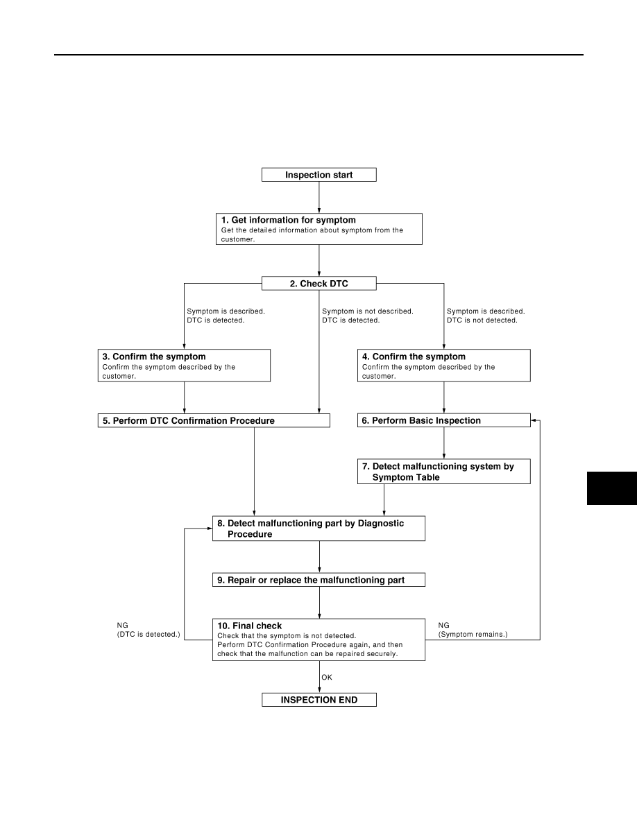
Work Flow
INFOID:0000000001116419
OVERALL SEQUENCE
DETAILED FLOW
JMKIA0101GB

SEC-6
< BASIC INSPECTION >
[WITH INTELLIGENT KEY SYSTEM]
DIAGNOSIS AND REPAIR WORKFLOW
1.
GET INFORMATION FOR SYMPTOM
Get the detailed information from the customer about the symptom (the condition and the environment when
the incident/malfunction occurred).
>> GO TO 2.
2.
CHECK DTC
1.
Check DTC for Intelligent Key unit and BCM.
2.
Perform the following procedure if DTC is displayed.
-
Erase DTC.
-
Study the relationship between the cause detected by DTC and the symptom described by the customer.
3.
Check related service bulletins for information.
Is any symptom described and any DTC detected?
Symptom is described, DTC is displayed>>GO TO 3.
Symptom is described, DTC is not displayed>>GO TO 4.
Symptom is not described, DTC is displayed>>GO TO 5.
3.
CONFIRM THE SYMPTOM
Confirm the symptom described by the customer.
Connect CONSULT-III to the vehicle in “DATA MONITOR” mode and check real-time diagnosis results.
Verify relation between the symptom and the condition when the symptom is detected.
>> GO TO 5.
4.
CONFIRM THE SYMPTOM
Confirm the symptom described by the customer.
Connect CONSULT-III to the vehicle in “DATA MONITOR ” mode and check real-time diagnosis results.
Verify relation between the symptom and the condition when the symptom is detected.
>> GO TO 6.
5.
PERFORM DTC CONFIRMATION PROCEDURE
Perform DTC Confirmation Procedure for the displayed DTC, and then check that DTC is detected again.
If two or more DTCs are detected, refer to
SEC-121, "DTC Inspection Priority Chart"
(Intelligent Key unit),
SEC-95, "DTC Inspection Priority Chart"
(BCM) and determine trouble diagnosis order.
Is DTC detected?
YES
>> GO TO 8.
NO
>> Refer to
GI-39, "Intermittent Incident"
.
6.
PERFORM BASIC INSPECTION
Perform Basic Inspection. Refer to
>> GO TO 7.
7.
DETECT MALFUNCTIONING SYSTEM BY SYMPTOM TABLE
Detect malfunctioning system according to Symptom Table based on the confirmed symptom in step 4.
>> GO TO 8.
8.
DETECT MALFUNCTIONING PART BY DIAGNOSTIC PROCEDURE
Inspect according to Diagnostic Procedure of the system.
NOTE:
The Diagnostic Procedure is described based on open circuit inspection. A short circuit inspection is also
required for the circuit check in the Diagnostic Procedure.
>> GO TO 9.
DIAGNOSIS AND REPAIR WORKFLOW
SEC-7
< BASIC INSPECTION >
[WITH INTELLIGENT KEY SYSTEM]
C
D
E
F
G
H
I
J
L
M
A
B
SEC
N
O
P
9.
REPAIR OR REPLACE THE MALFUNCTIONING PART
1.
Repair or replace the malfunctioning part.
2.
Reconnect parts or connectors disconnected during Diagnostic Procedure again after repair and replace-
ment.
3.
Check DTC. If DTC is displayed, erase it.
>> GO TO 10.
10.
FINAL CHECK
When DTC was detected in step 9, perform DTC Confirmation Procedure or Component Function Check
again, and then check that the malfunctions have been fully repaired.
When symptom was described by the customer, refer to the confirmed symptom in step 3 or 4, and check that
the symptom is not detected.
Does the symptom reappear?
YES (DTC is detected)>>GO TO 8.
YES (Symptom remains)>>GO TO 6.
NO
>> INSPECTION END
Нет комментариевНе стесняйтесь поделиться с нами вашим ценным мнением.
Текст