Nissan Qashqai (2007-2010). Manual — part 1359
IPDM E/R (INTELLIGENT POWER DISTRIBUTION MODULE ENGINE ROOM)
EXL-141
< ECU DIAGNOSIS >
[XENON TYPE]
C
D
E
F
G
H
I
J
K
M
A
B
EXL
N
O
P
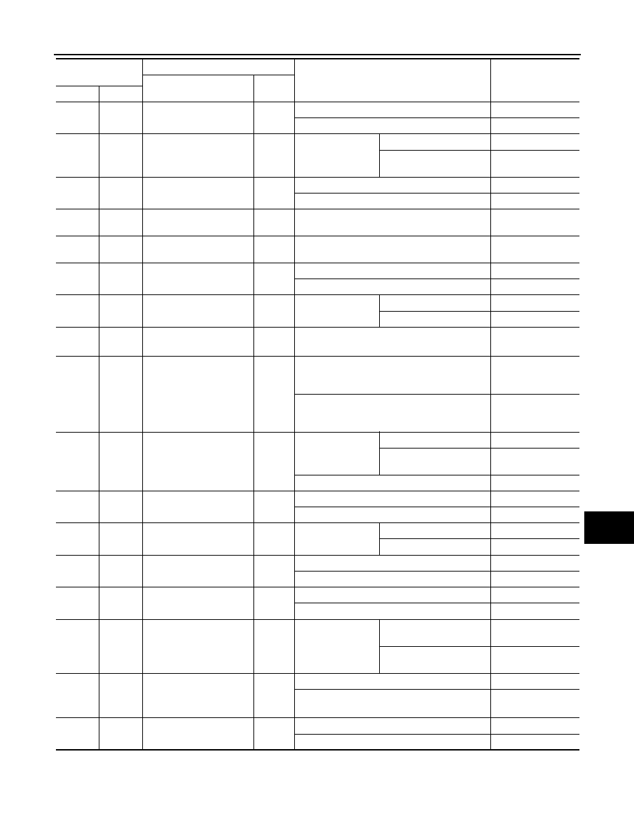
25*
1
(G/L)
Ground
ETC relay control
Input
Ignition switch OFF or ACC
Battery voltage
Ignition switch ON
0 - 1.0 V
26
(O)
Ground
Front wiper auto stop
Input
Ignition switch ON
Front wiper stop position
0 V
Any position other than
front wiper stop position
Battery voltage
27
(W)
Ground
Oil pressure switch
Input
Engine stopped
0 V
Engine running
Battery voltage
28
(L)
—
CAN-H
Input/
Output
—
—
29
(P)
—
CAN-L
Input/
Output
—
—
30*
4
(L)
Ground
Horn relay control
Output
The horn is not activated
Battery voltage
The horn is activated
0 V
31
(R)
Ground
Headlamp LO (sensor)
Output
Ignition switch ON
Lighting switch OFF
0 V
Lighting switch 2ND
Battery voltage
32*
1
(R/Y)
Ground
ETC relay power supply
Output
Ignition switch ON
Battery voltage
33*
1
(B/O)
Ground
Fuel pump relay control
Input
• Engine running
• Ignition switch ON
(For 1 second after turning ignition switch ON)
0 - 1.0 V
Ignition switch ON
(More than 1 second after turning ignition switch
ON)
Battery voltage
34
(R/B)
Ground
Starter relay power supply
Input
Ignition switch ON
(Except M/T mod-
els)
Selector lever “P” or “N”
0 V
Selector lever in any posi-
tion other than “P” or “N”
Battery voltage
Ignition switch ON (M/T models)
35
(W/L)
Ground
Ignition switch ON
Input
Ignition switch OFF or ACC
0 V
Ignition switch ON
Battery voltage
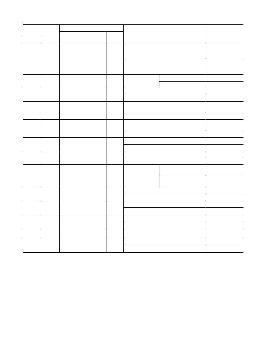
36
(W)
Ground
Front fog lamp (RH)
Output
Lighting switch 1ST
Front fog lamp switch ON
Battery voltage
Front fog lamp switch OFF
0 V
37
(R/W)
Ground
Parking lamp (RH)
Output
Lighting switch 1ST
Battery voltage
Lighting switch OFF
0 V
38
(R/L)
Ground
Tail, license plate lamps
and illuminations
Output
Lighting switch 1ST
Battery voltage
Lighting switch OFF
0 V
39
(GR)
Ground
Headlamp washer relay
control
Output
Ignition switch ON
When headlamp washer is
operating
0 V
When headlamp washer is
not operating
Battery voltage
40*
1
(BR/Y)*
5
(SB)*
6
Ground
Ignition relay power supply
Output
Ignition switch OFF or ACC
0 V
Ignition switch ON
Battery voltage
41
(P)
Ground
Ignition relay power supply
Output
Ignition switch OFF or ACC
0 V
Ignition switch ON
Battery voltage
Terminal No.
(Wire color)
Description
Condition
Value
(Approx.)
Signal name
Input/
Output
+
−
EXL-142
< ECU DIAGNOSIS >
[XENON TYPE]
IPDM E/R (INTELLIGENT POWER DISTRIBUTION MODULE ENGINE ROOM)
*
1
: HR engine and MR engine models
*
2
: K9K engine models
*
3
: Except M/T models only
*
4
: With vehicle security (theft warning) system
*
5
: HR engine models
*
6
: MR engine models
*
7
: MR engine and K9K engine models
42*
1
(B/Y)
Ground
Fuel pump relay power
supply
Output
• Ignition switch OFF or ACC
• Approximately 1 second or more after turning
the ignition switch ON
0 V
• Approximately 1 second after turning the igni-
tion switch ON
• Engine running
Battery voltage
43
(W/B)
Ground
Front fog lamp (LH)
Output
Lighting switch 1ST
Front fog lamp switch ON
Battery voltage
Front fog lamp switch OFF
0 V
44
(L)
Ground
Headlamp LO (LH)
Output
Lighting switch OFF
0 V
Lighting switch 2ND
Battery voltage
45
(L/W)
Ground
Headlamp HI (RH)
Output
• Lighting switch 2ND and HI
• lighting switch PASS
Battery voltage
Lighting switch OFF
0 V
46
(G)
Ground
Headlamp HI (LH)
Output
• Lighting switch 2ND and HI
• Lighting switch PASS
Battery voltage
Lighting switch OFF
0 V
47
(R/L)
Ground
Parking lamp (LH)
Output
Lighting switch 1ST
Battery voltage
Lighting switch OFF
0 V
48*
7
(Y)
Ground
Cooling fan relay-3 control
Output
When cooling fan does HI operation
0 V
When cooling fan does OFF or LO operation
Battery voltage
49
(B)
Ground
Rear window defogger re-
lay power supply
Output
Ignition switch ON
Rear window defogger
switch ON
Battery voltage
Rear window defogger
switch OFF
0 V
50
(B/R)
Ground
Starter relay power supply
Output
When engine is clanking
Battery voltage
When engine is not clanking
0 V
51
(P)
Ground
Ignition switch START
Input
Ignition switch START
Battery voltage
Ignition switch OFF, ACC or ON
0 V
52
(W)
Ground
Cooling fan relay-1 power
supply
Output
When cooling fan does LO or HI operation
Battery voltage
When cooling fan does OFF operation
0 V
53
(W/B)
Ground
Battery power supply
(Cooling fan relay)
Input
Ignition switch OFF
Battery voltage
54*
5
(R)
Ground
Cooling fan relay-2 power
supply
Input
When cooling fan does HI operation
Battery voltage
When cooling fan does OFF or LO operation
0 V
Terminal No.
(Wire color)
Description
Condition
Value
(Approx.)
Signal name
Input/
Output
+
−
IPDM E/R (INTELLIGENT POWER DISTRIBUTION MODULE ENGINE ROOM)
EXL-143
< ECU DIAGNOSIS >
[XENON TYPE]
C
D
E
F
G
H
I
J
K
M
A
B
EXL
N
O
P
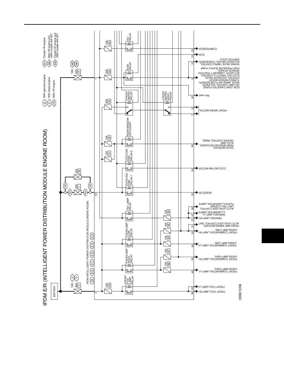
Wiring Diagram - IPDM E/R -
INFOID:0000000001098958
JCMWA0420GB
EXL-144
< ECU DIAGNOSIS >
[XENON TYPE]
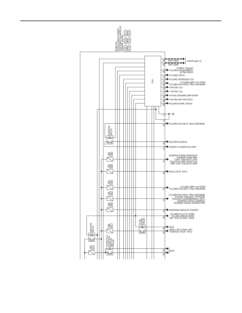
IPDM E/R (INTELLIGENT POWER DISTRIBUTION MODULE ENGINE ROOM)
JCMWA0421GB
Нет комментариевНе стесняйтесь поделиться с нами вашим ценным мнением.
Текст