Nissan Qashqai (2007-2010). Manual — part 639

REAR FINAL DRIVE ASSEMBLY
DLN-129
< REMOVAL AND INSTALLATION >
[REAR FINAL DRIVE: R145]
C
E
F
G
H
I
J
K
L
M
A
B
DLN
N
O
P
- Install rear final drive breather hose (1) to breather connector (2).
Install bracket (3) to the breather connector. Check that the paint
mark (A) of metal connector (4) faces forward of the vehicle as
shown by the arrow.
- Install electric controlled coupling breather hose (1) to metal tube
all way to the point shown by the solid arrow. Check that the cou-
pling cover (2) of metal tube (3) faces forward of the vehicle as
shown by the outline arrow (
).
• When oil leaks while removing final drive assembly, check oil level
after the installation. Refer to
: Vehicle front
JSDIA0222ZZ
: Vehicle front
JSDIA0223ZZ
DLN-130
< DISASSEMBLY AND ASSEMBLY >
[REAR FINAL DRIVE: R145]
ELECTRIC CONTROLLED COUPLING
DISASSEMBLY AND ASSEMBLY
ELECTRIC CONTROLLED COUPLING
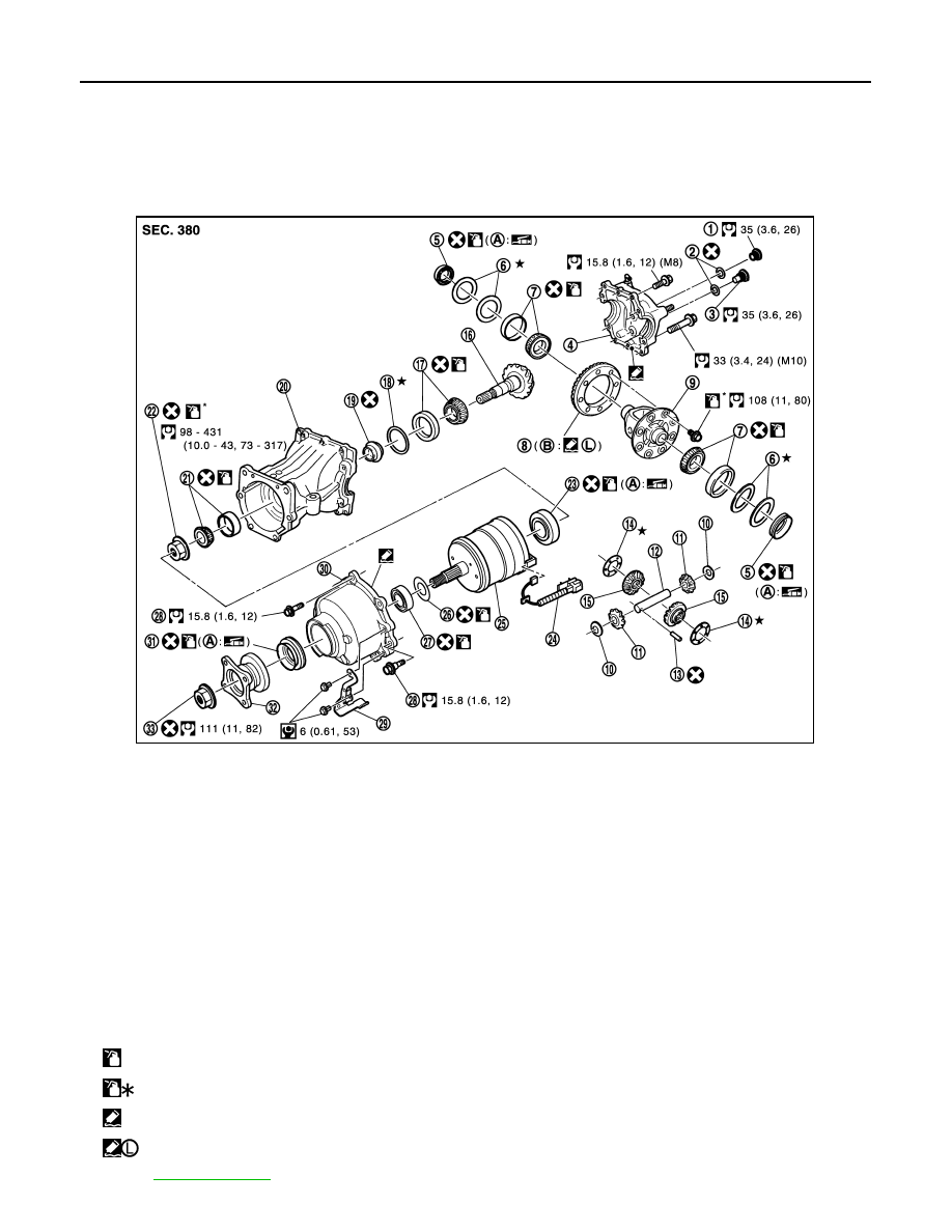
Exploded View
INFOID:0000000001076996
1.
Filler plug
2.
Gasket
3.
Drain plug
4.
Rear cover
5.
Side oil seal
6.
Side bearing adjusting shim
7.
Side bearing
8.
Drive gear
9.
Differential case
10. Pinion mate thrust washer
11.
Pinion mate gear
12. Pinion mate shaft
13. Lock pin
14. Side gear thrust washer
15. Side gear
16. Drive pinion
17. Pinion rear bearing
18. Drive pinion adjusting shim
19. Collapsible spacer
20. Gear carrier
21. Pinion front bearing
22. Drive pinion nut
23. Center oil seal
24. 4WD solenoid harness
25. Electric controlled coupling
26. Bearing shim
27. Coupling front bearing
28. Reamer bolt
29. Connector bracket
30. Coupling cover
31. Front oil seal
32. Companion flange
33. Companion flange lock nut
A: Oil seal lip
B: Screw hole
: Apply gear oil.
: Apply anti-corrosive oil.
: Apply Genuine Liquid Gasket, Three Bond TB1217 or equivalent.
: Apply Genuine Medium Strength Thread Locking Sealant, Three Bond TB1322B or equivalent.
Refer to
for symbols not described on the above.
JSDIA0234GB
ELECTRIC CONTROLLED COUPLING
DLN-131
< DISASSEMBLY AND ASSEMBLY >
[REAR FINAL DRIVE: R145]
C
E
F
G
H
I
J
K
L
M
A
B
DLN
N
O
P
Disassembly
INFOID:0000000001076997
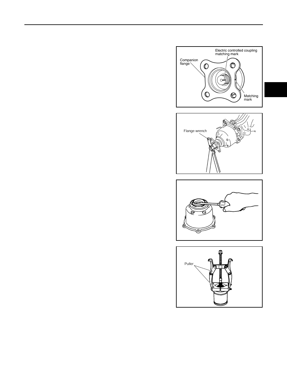
1.
Remove connector bracket.
2.
Put matching mark on the thread edge of electric controlled cou-
pling. The matching mark should be in line with the matching
mark on companion flange.
CAUTION:
For matching mark, use paint. Never damage electric con-
trolled coupling.
NOTE:
When replacing electric controlled coupling, matching mark is
not necessary.
3.
Remove companion flange lock nut, using a flange wrench
(commercial service tool).
4.
Remove companion flange.
5.
Remove coupling cover.
6.
Remove front oil seal from coupling cover, using flat-bladed
screwdriver.
CAUTION:
Be careful not to damage coupling cover.
7.
Remove electric controlled coupling.
8.
Remove 4WD solenoid harness.
9.
Remove coupling front bearing, using pullers and then take off
bearing shim from electric controlled coupling.
10. Remove center oil seal from gear carrier.
Assembly
INFOID:0000000001076998
PDIA0455E
PDIA0442E
PDG0213D
PDIA0444E
DLN-132
< DISASSEMBLY AND ASSEMBLY >
[REAR FINAL DRIVE: R145]
ELECTRIC CONTROLLED COUPLING
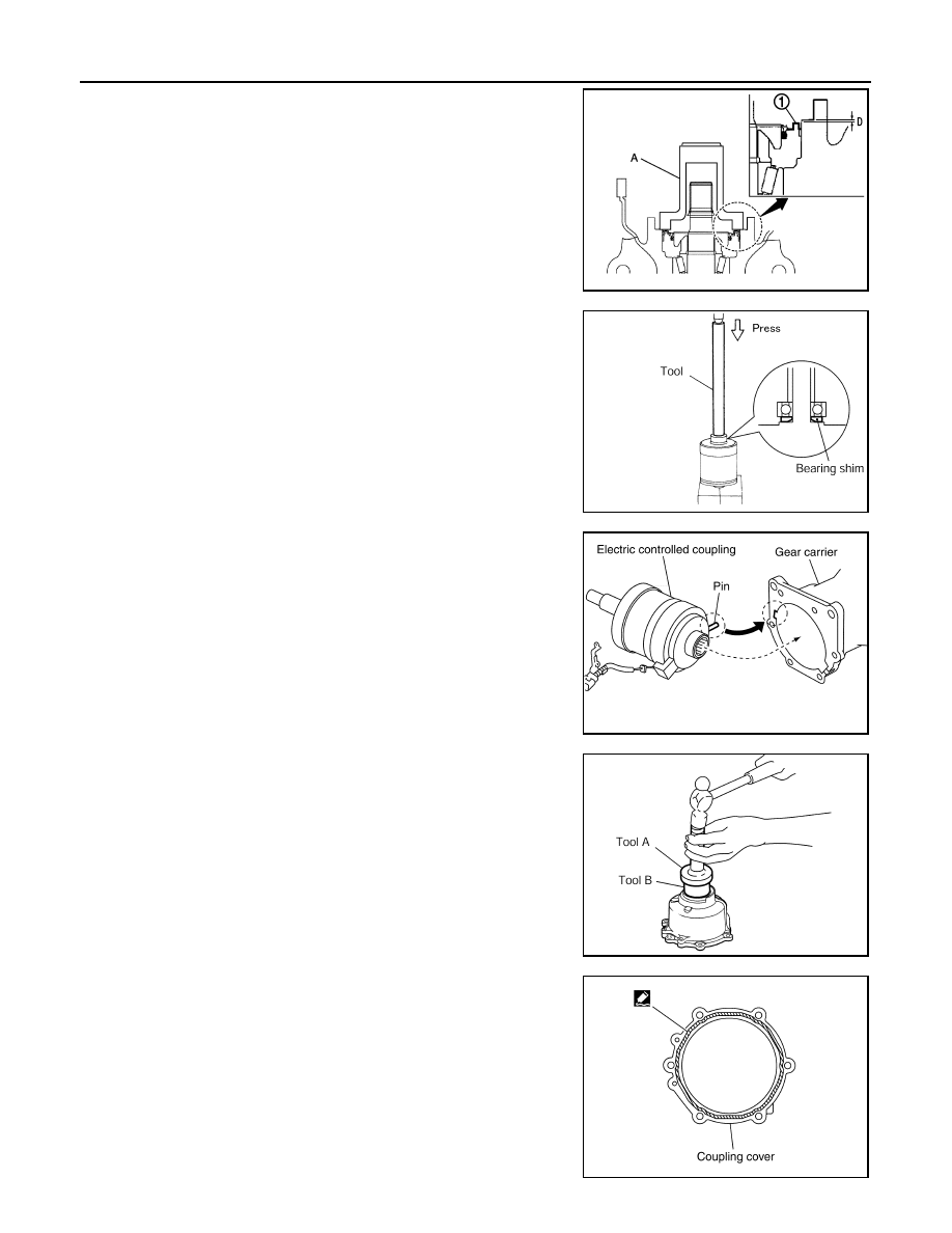
1.
Using the drift (A) (SST: ST35271000), install center oil seal (1)
as shown in the figure.
CAUTION:
• Never reuse oil seal.
• When installing, never incline oil seal.
• Apply multi-purpose grease onto oil seal lips, and gear oil
onto the circumference of oil seal.
2.
Install bearing shim and coupling front bearing to electric con-
trolled coupling, using the drift (SST: 22360002).
CAUTION:
• Never reuse bearing shim and coupling front bearing.
• When assembling bearing shim, shim chamfer side
should face electric controlled coupling side.
• Apply gear oil to coupling front bearing and bearing shim.
3.
Connect 4WD solenoid harness to electric controlled coupling.
4.
Install electric controlled coupling to spline of drive pinion inside
gear carrier.
CAUTION:
• Align the pin on electric controlled coupling with the
groove of gear carrier.
• Be careful not to damage center oil seal.
5.
Set 4WD solenoid harness guide to gear carrier.
6.
Using the drifts, drive front oil seal until it becomes flush with the
coupling cover end.
CAUTION:
• Never reuse oil seal.
• When installing, never incline oil seal.
• Apply multi-purpose grease onto oil seal lips, and gear oil
onto the circumference of oil seal.
7.
Apply liquid gasket to mating surface of coupling cover. Overlap
both ends of the bead for at least 3 mm (0.12 in).
CAUTION:
Remove old gasket adhering to the mounting surfaces.
Also remove any moisture, oil, or foreign material adhering
to the mounting surfaces.
Dimension “D”
: 0.8 – 1.2 mm (0.031 – 0.047 in)
JSDIA0260ZZ
PDIA0450E
PDIA0463E
A
: Drift (SST: KV38100200)
B
: Drift (SST: ST27861000)
PDIA0449E
PDIA0613E
Нет комментариевНе стесняйтесь поделиться с нами вашим ценным мнением.
Текст