Nissan Qashqai (2007-2010). Manual — part 1372
DAYTIME RUNNING LIGHT SYSTEM
EXL-193
< FUNCTION DIAGNOSIS >
[HALOGEN TYPE]
C
D
E
F
G
H
I
J
K
M
A
B
EXL
N
O
P
DAYTIME RUNNING LIGHT SYSTEM
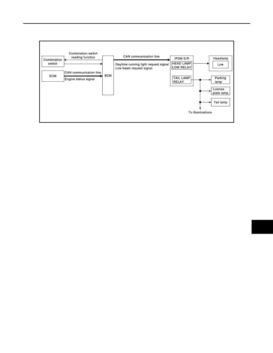
System Diagram
INFOID:0000000001099320
System Description
INFOID:0000000001099321
OUTLINE
• Turns the following exterior lamps ON as the daytime running light.
- headlamp (LO)
- Tail lamp, parking lamp and license plate lamp
• Daytime running light is controlled by daytime running light control function and combination switch reading
function of BCM, and relay control function of IPDM E/R.
DAYTIME RUNNING LIGHT OPERATION
• BCM detects the combination switch condition by the combination switch reading function.
• BCM detects the engine condition by the engine status signal received from ECM with CAN communication.
• BCM transmits the daytime running light request signal and low beam request signal to IPDM E/R with CAN
communication according to the daytime running light ON condition.
Daytime running light ON condition
- Engine running
- Lighting switch OFF or AUTO
• IPDM E/R turns the integrated headlamp low relay and tail lamp relay ON according to the daytime running
light request signal and low beam request signal. And it turns each lamps ON.
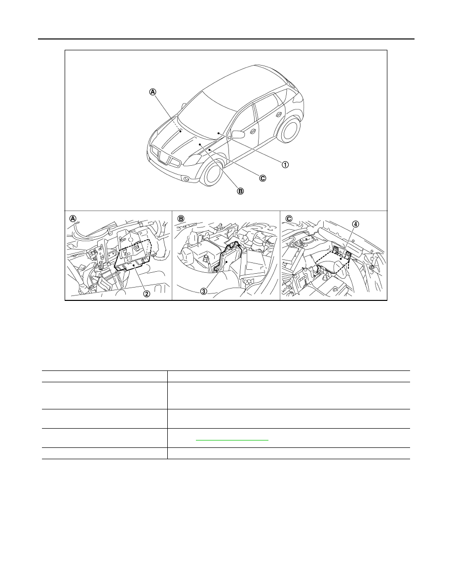
Component Parts Location
INFOID:0000000001099322
JPLIA0170GB
EXL-194
< FUNCTION DIAGNOSIS >
[HALOGEN TYPE]
DAYTIME RUNNING LIGHT SYSTEM
Component Description
INFOID:0000000001099323
1.
Combination switch
2.
BCM
3.
ECM
4.
IPDM E/R
A.
Over the glove box
B.
Engine room (left side)
C.
Engine room (left side)
JPLIA0191ZZ
Part
Description
BCM
• Detects each switch condition with the combination switch reading function.
• Judges each lamps ON/OFF condition according to the vehicle condition. Requests
the each relay ON to IPDM E/R (with CAN communication).
IPDM E/R
Controls the integrated relay and supplies voltage to the load according to the request
from BCM (with CAN communication).
Combination switch
(Lighting & turn signal switch)
Refer to
.
ECM
Transmits the engine status signal to BCM with CAN communication.
AUTO LIGHT SYSTEM
EXL-195
< FUNCTION DIAGNOSIS >
[HALOGEN TYPE]
C
D
E
F
G
H
I
J
K
M
A
B
EXL
N
O
P
AUTO LIGHT SYSTEM
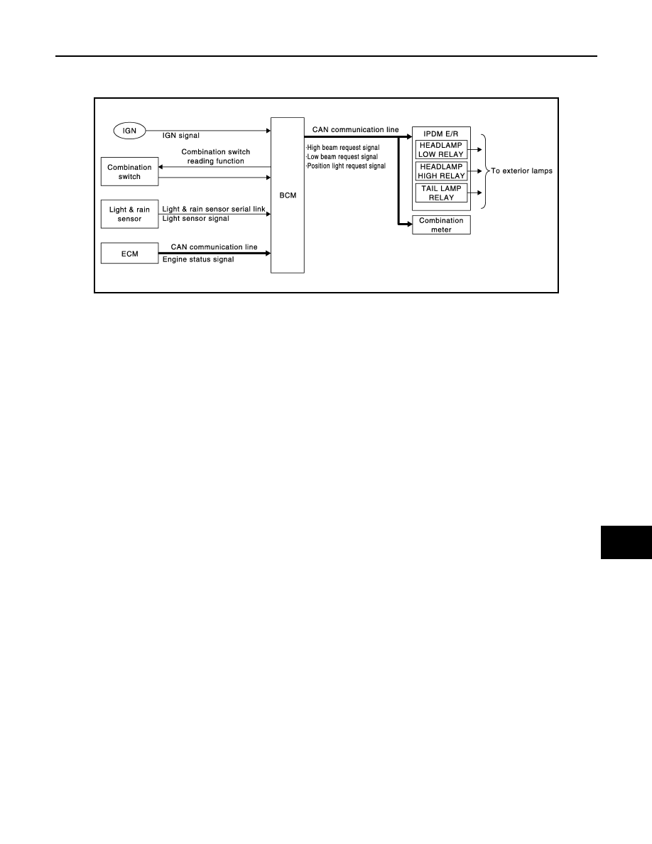
System Diagram
INFOID:0000000001099324
System Description
INFOID:0000000001099325
OUTLINE
• Auto light system is controlled by each function of BCM and IPDM E/R.
Control by BCM
- Combination switch reading function
- Headlamp control function
- Auto light function
Control by IPDM E/R
- Relay control function
• Auto light function turns the exterior lamps* ON/OFF automatically according to the outside brightness.
*: Headlamp (LO/HI), parking lamp, tail lamp (Headlamp HI depends on the combination switch condition.)
AUTO LIGHT FUNCTION
• BCM detects the combination switch condition with the combination switch reading function.
• BCM detects the engine condition by the engine status signal received from ECM with CAN communication.
• BCM receives the light sensor signal [outside brightness (lux) and the light & rain sensor condition] from light
& rain sensor with the light & rain sensor serial link.
• BCM judges ON/OFF condition of the exterior lamps according to the outside brightness and the vehicle
condition.
• BCM transmits each request signal to IPDM E/R with CAN communication according to ON/OFF condition
by the auto light function.
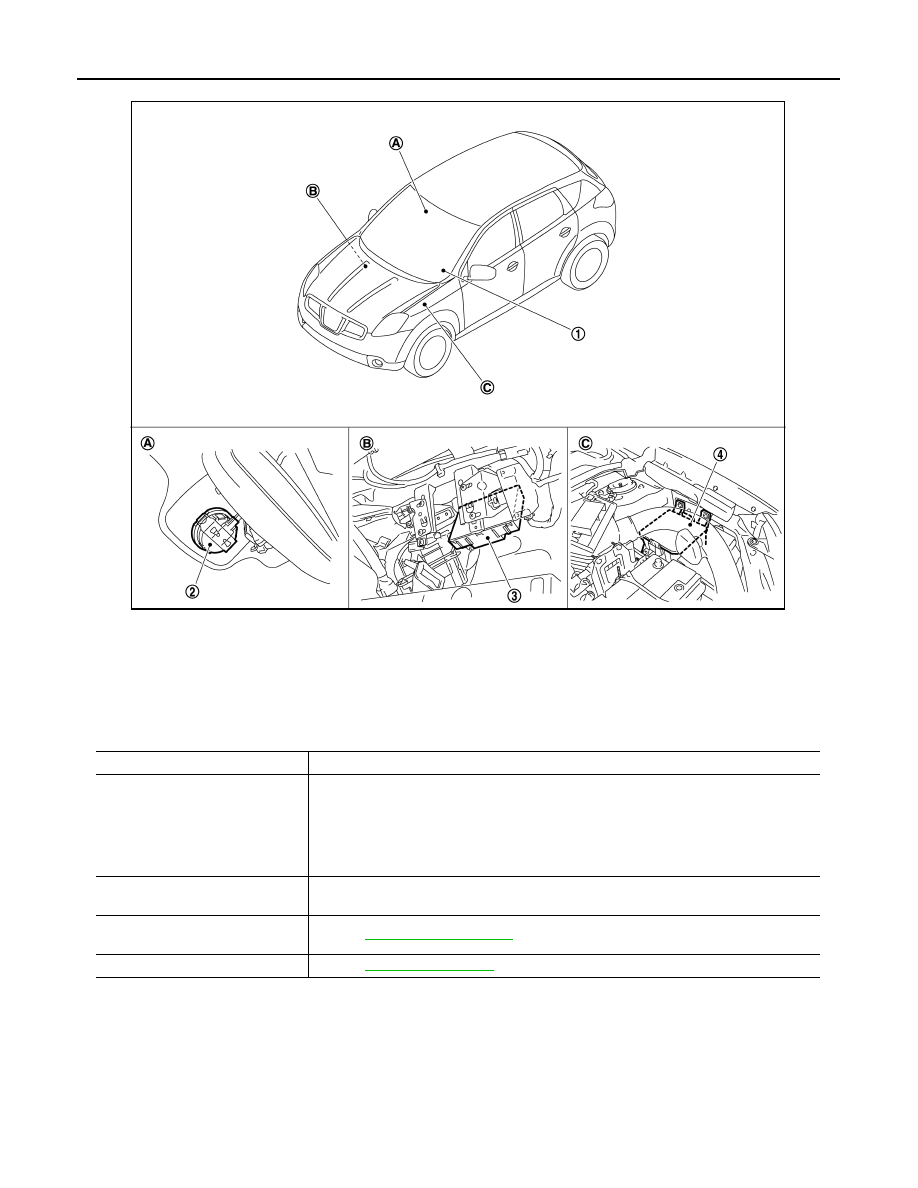
Component Parts Location
INFOID:0000000001099326
JPLIA0169GB
EXL-196
< FUNCTION DIAGNOSIS >
[HALOGEN TYPE]
AUTO LIGHT SYSTEM
Component Description
INFOID:0000000001099327
1.
Combination switch
2.
Light & rain sensor
3.
BCM
4.
IPDM E/R
A.
Windshield upper
B.
Over the glove box
C.
Engine room (left side)
JPLIA0194ZZ
Part
Description
BCM
• Detects each switch condition by the combination switch reading function.
• Detects the outside brightness from the light & rain sensor by light & rain sensor serial
link.
• Judges the ON/OFF status of the exterior lamp according to the outside brightness and
the vehicle condition.
• Requests ON/OFF of each relay to IPDM E/R (with CAN communication).
IPDM E/R
Controls the integrated relay, and supplies voltage to the load according to the request
from BCM (with CAN communication).
Combination switch
(Lighting & turn signal switch)
Light & rain sensor
.
Нет комментариевНе стесняйтесь поделиться с нами вашим ценным мнением.
Текст