Nissan Qashqai (2007-2010). Manual — part 69
EM-224
< DISASSEMBLY AND ASSEMBLY >
[MR20DE]
CYLINDER BLOCK
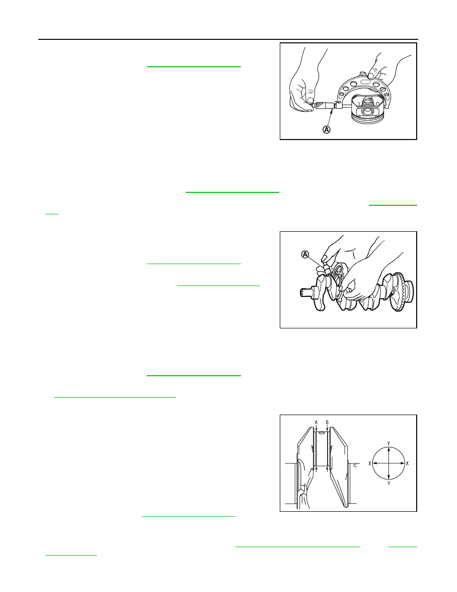
Measure the outer diameter of piston skirt with a micrometer (A).
Piston to Cylinder Bore Clearance
Calculate by piston skirt diameter and cylinder bore inner diameter (direction “X”, position “B”).
(Clearance) = (Cylinder bore inner diameter) – (Piston skirt diameter)
• If it exceeds the limit, replace piston and piston pin assembly and/or cylinder block. Refer to
.
CRANKSHAFT MAIN JOURNAL DIAMETER
• Measure the outer diameter of crankshaft main journals with a
micrometer (A).
• If out of the standard, measure the main bearing oil clearance.
Then use undersize bearing. Refer to
CRANKSHAFT PIN JOURNAL DIAMETER
• Measure the outer diameter of crankshaft pin journal with a micrometer.
• If out of the standard, measure the connecting rod bearing oil clearance. Then use undersize bearing. Refer
EM-244, "Connecting Rod Bearing"
.
OUT-OF-ROUND AND TAPER OF CRANKSHAFT
• Measure the dimensions at four different points as shown in the
figure on each main journal and pin journal with a micrometer.
• Out-of-round is indicated by the difference in dimensions between
“X” and “Y” at “A” and “B”.
• Taper is indicated by the difference in dimension between “A” and
“B” at “X” and “Y”.
• If the measured value exceeds the limit, correct or replace crankshaft.
• If corrected, measure the bearing oil clearance of the corrected main journal and/or pin journal. Then select
main bearing and/or connecting rod bearing. Refer to
EM-244, "Connecting Rod Bearing"
CRANKSHAFT RUNOUT
Standard :
PBIC3272J
Standard and Limit
: Refer to
.
Standard :
PBIC3457J
Standard :
Limit:
Out-of-round (Difference between“X”and“Y”)
Taper (Difference between“A”and“B”)
: Refer to
.
PBIC3459J
CYLINDER BLOCK
EM-225
< DISASSEMBLY AND ASSEMBLY >
[MR20DE]
C
D
E
F
G
H
I
J
K
L
M
A
EM
N
P
O
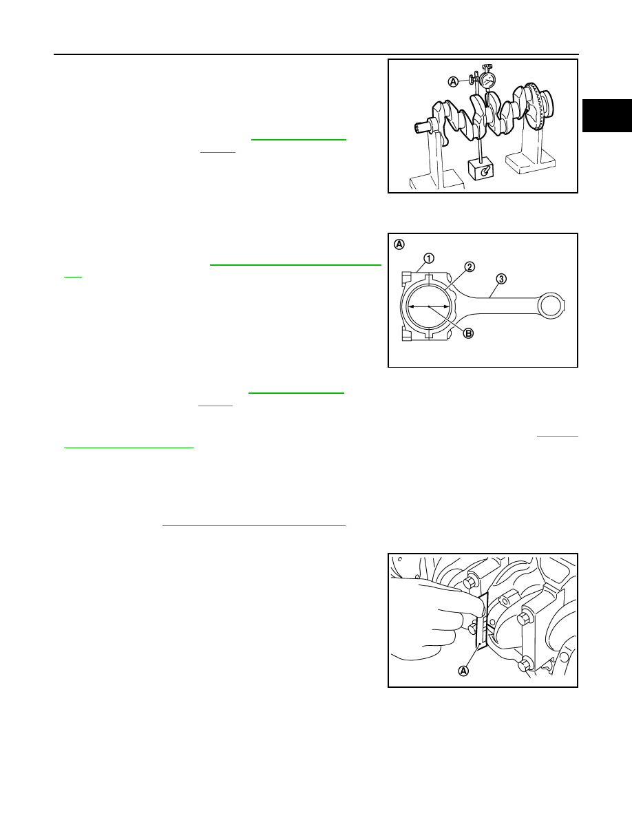
• Place a V-block on a precise flat table to support the journals on
the both end of the crankshaft.
• Place a dial indicator (A) straight up on the No. 3 journal.
• While rotating crankshaft, read the movement of the pointer on the
dial indicator. (Total indicator reading)
• If it exceeds the limit, replace crankshaft.
CONNECTING ROD BEARING OIL CLEARANCE
Method by Calculation
• Install connecting rod bearings (2) to connecting rod (3) and con-
necting rod bearing cap (1), and tighten connecting rod cap bolts to
the specified torque. Refer to
EM-211, "Disassembly and Assem-
• Measure the inner diameter of connecting rod bearing with an
inside micrometer.
(Bearing oil clearance) = (Connecting rod bearing inner diameter)
– (Crankshaft pin journal diameter)
• If clearance exceeds the limit, select proper connecting rod bearing according to connecting rod big end
diameter and crankshaft pin journal diameter to obtain specified bearing oil clearance. Refer to
.
Method of Using Plastigage
• Remove engine oil and dust on crankshaft pin and the surfaces of each bearing completely.
• Cut a plastigage slightly shorter than the bearing width, and place it in crankshaft axial direction, avoiding oil
holes.
• Install connecting rod bearings to connecting rod and cap, and tighten connecting rod cap bolts to the speci-
EM-211, "Disassembly and Assembly"
CAUTION:
Never rotate crankshaft.
• Remove connecting rod cap and bearing, and using the scale (A)
on the plastigage bag, measure the plastigage width.
NOTE:
The procedure when the measured value exceeds the limit is
same as that described in the “Method by Calculation”.
MAIN BEARING OIL CLEARANCE
Method by Calculation
Standard and Limit
: Refer to
PBIC3458J
A
: Example
B
: Inner diameter measuring direction
Standard and Limit
: Refer to
.
PBIC3275J
PBIC3276J
EM-226
< DISASSEMBLY AND ASSEMBLY >
[MR20DE]
CYLINDER BLOCK
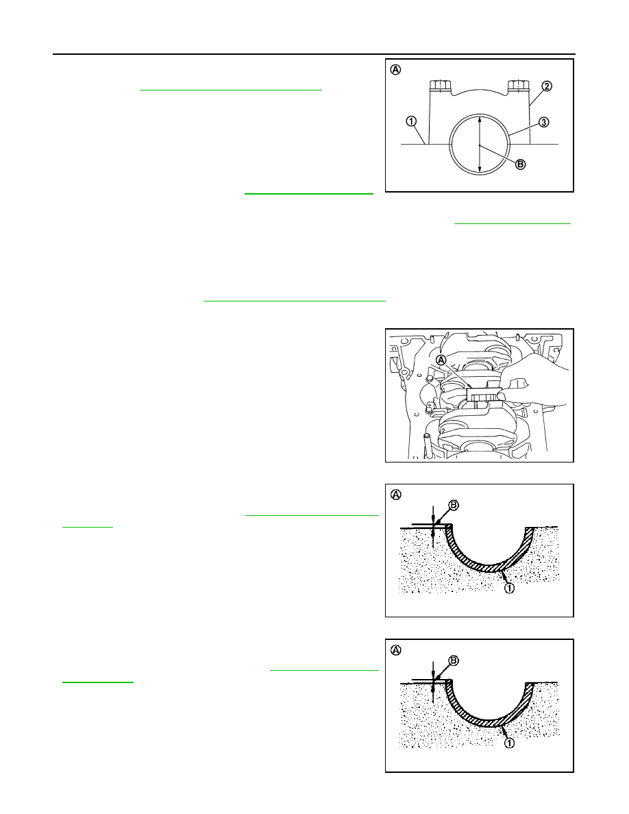
• Install main bearings (3) to cylinder block (1) and main bearing cap
(2), and tighten main bearing cap mounting bolts to the specified
torque. Refer to
EM-211, "Disassembly and Assembly"
.
• Measure the inner diameter of main bearing with a bore gauge.
(Bearing oil clearance) = (Main bearing inner diameter) – (Crank-
shaft main journal diameter)
• If clearance exceeds the limit, select proper main bearing according to main bearing inner diameter and
crankshaft main journal diameter to obtain specified bearing oil clearance. Refer to
.
Method of Using Plastigage
• Remove engine oil and dust on crankshaft main journal and the surfaces of each bearing completely.
• Cut a plastigage slightly shorter than the bearing width, and place it in crankshaft axial direction, avoiding oil
holes.
• Install main bearings to cylinder block and main bearing cap, and tighten main bearing cap mounting bolts to
the specified torque. Refer to
EM-211, "Disassembly and Assembly"
CAUTION:
Never rotate crankshaft.
• Remove main bearing cap and bearings, and using the scale (A)
on the plastigage bag, measure the plastigage width.
NOTE:
The procedure when the measured value exceeds the limit is
same as that described in the “Method by Calculation”.
MAIN BEARING CRUSH HEIGHT
• When main bearing cap is removed after being tightened to the
specified torque with main bearings (1) installed, the tip end of
bearing must protrude (B). Refer to
• If the standard is not met, replace main bearings.
CONNECTING ROD BEARING CRUSH HEIGHT
• When connecting rod cap is removed after being tightened to the
specified torque with connecting rod bearings (1) installed, the tip
end of bearing must protrude (B). Refer to
.
• If the standard is not met, replace connecting rod bearings.
A
: Example
B
: Inner diameter measuring direction
Standard and Limit
: Refer to
PBIC3277J
PBIC3278J
A
: Example
Standard
: There must be crush height.
PBIC3279J
A
: Example
Standard
: There must be crush height.
PBIC3279J
CYLINDER BLOCK
EM-227
< DISASSEMBLY AND ASSEMBLY >
[MR20DE]
C
D
E
F
G
H
I
J
K
L
M
A
EM
N
P
O
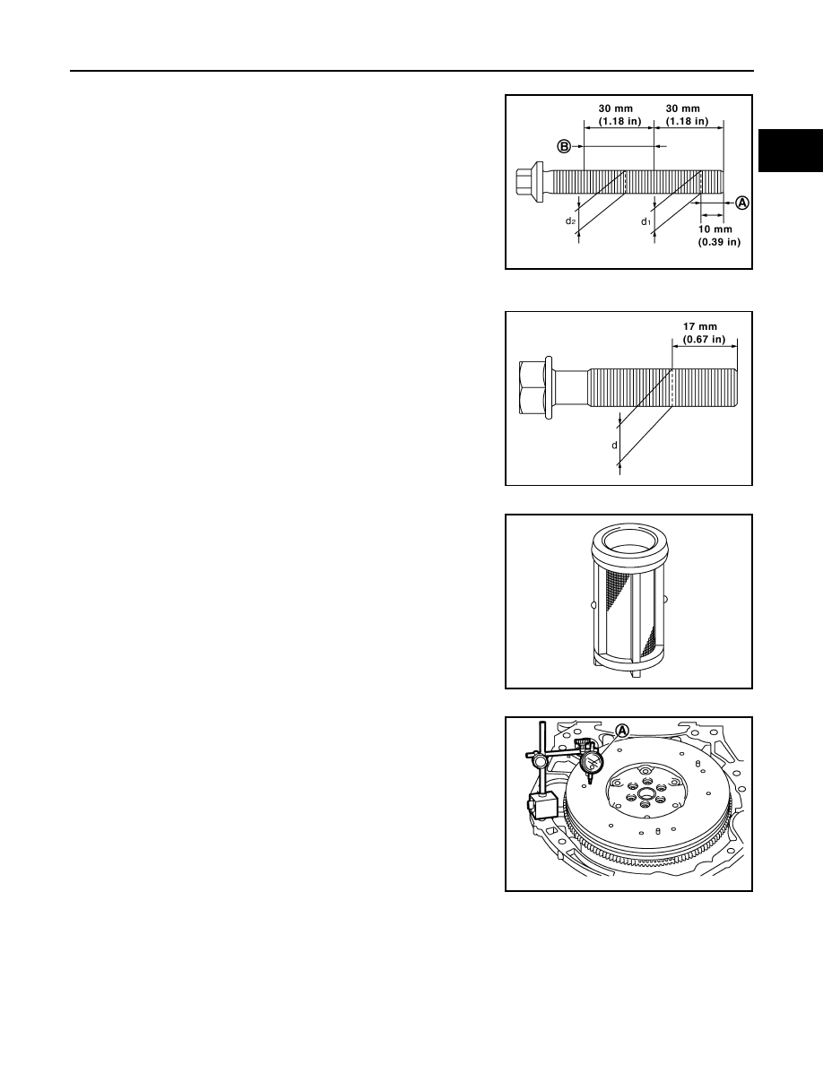
MAIN BEARING CAP BOLT OUTER DIAMETER
• Measure the outer diameters (“d
1
”, “d
2”
) at two positions as shown
in the figure.
• If reduction appears in places other than “B” range, regard it as
“d
2
”.
• If it exceeds the limit (a large difference in dimensions), replace
main bearing cap mounting bolt with a new one.
CONNECTING ROD CAP BOLT OUTER DIAMETER
• Measure the outer diameter “d” at position as shown in the figure.
• If reduction appears in a position other than “d”, regard it as “d”.
• When “d” exceeds the limit (when it becomes thinner), replace
connecting rod cap bolt with a new one.
CLOGGED OR DAMAGED OIL FILTER (FOR INTAKE VALVE TIMING CONTROL)
• Make sure that there is no foreign material on the oil filter and
check it for clogging.
- Clean it if necessary.
• Check the oil filter for damage.
- Replace it if necessary.
FLYWHEEL DEFLECTION (M/T MODELS)
• Measure the deflection of flywheel contact surface to torque with a
dial indicator (A).
• Measure the deflection at 210 mm (8.27 in) diameter.
• If measured value is out of the standard, replace flywheel.
• If a trace of burn or discoloration is found on the surface, repair it
with sandpaper.
CAUTION:
When measuring, keep magnetic fields (such as dial indicator
stand) away from signal plate of the rear end of crankshaft.
MOVEMENT AMOUNT OF FLYWHEEL (M/T MODELS)
CAUTION:
Never disassemble double mass flywheel.
Movement Amount of Thrust (Fore-and-Aft) Direction
• Measure the movement amount of thrust (fore-and-aft) direction when 100 N (10.2 kg, 22 lb) force is added
at the portion of 125 mm (4.92 in) radius from the center of flywheel.
A
: “d1” measuring position
B
: “d2” measuring position
Limit (“d
1
”–“d
2
”): 0.15 mm (0.0059 in)
PBIC4015E
Limit: 7.75 mm (0.3051 in)
PBIC4016E
PBIC3273J
Limit : 0.45 mm (0.0177 in) or less.
PBIC4006E
Нет комментариевНе стесняйтесь поделиться с нами вашим ценным мнением.
Текст