Nissan Pathfinder (2009 year). Instruction — part 317

EC-550
< FUNCTION DIAGNOSIS >
[VK56DE]
ON BOARD DIAGNOSTIC (OBD) SYSTEM
*: The item is the same as that of 1st trip freeze frame data.
DATA MONITOR MODE
Monitored Item
×
: Applicable
INT MANI PRES [kPa]
• These items are displayed but are not applicable to this models.
COMBUST CONDITION
Freeze frame data item*
Description
Monitored item
Unit
Description
Remarks
ENG SPEED
rpm
• Indicates the engine speed computed from the
signal of the crankshaft position sensor (POS)
and camshaft position sensor (PHASE).
• Accuracy becomes poor if engine speed
drops below the idle rpm.
• If the signal is interrupted while the engine
is running, an abnormal value may be indi-
cated.
MAS A/F SE-B1
V
• The signal voltage of the mass air flow sensor is
displayed.
• When the engine is stopped, a certain value
is indicated.
• When engine is running, specification range
is indicated in “SPEC”.
B/FUEL SCHDL
ms
• Base fuel schedule indicates the fuel injection
pulse width programmed into ECM, prior to any
learned on board correction.
• When engine is running, specification range
is indicated in “SPEC”.
A/F ALPHA-B1
%
• The mean value of the air-fuel ratio feedback cor-
rection factor per cycle is indicated.
• When the engine is stopped, a certain value
is indicated.
• When engine is running, specification range
is indicated in “SPEC”.
• This data also includes the data for the air-
fuel ratio learning control.
A/F ALPHA-B2
%
COOLAN TEMP/S
°
C or
°
F
• The engine coolant temperature (determined by
the signal voltage of the engine coolant tempera-
ture sensor) is displayed.
• When the engine coolant temperature sen-
sor is open or short-circuited, ECM enters
fail-safe mode. The engine coolant temper-
ature determined by the ECM is displayed.
A/F SEN1 (B1)
V
• The A/F signal computed from the input signal of
the A/F sensor 1 is displayed.
A/F SEN1 (B2)
V
HO2S2 (B1)
V
• The signal voltage of the heated oxygen sensor 2
is displayed.
HO2S2 (B2)
V
HO2S2 MNTR (B1)
RICH/
LEAN
• Display of heated oxygen sensor 2 signal:
RICH: means the amount of oxygen after three
way catalyst is relatively small.
LEAN: means the amount of oxygen after three
way catalyst is relatively large.
• When the engine is stopped, a certain value
is indicated.
HO2S2 MNTR (B2)
RICH/
LEAN
VHCL SPEED SE
km/h or
mph
• The vehicle speed computed from the vehicle
speed signal sent from unified meter control unit
is displayed.
BATTERY VOLT
V
• The power supply voltage of ECM is displayed.
ACCEL SEN 1
V
• The accelerator pedal position sensor signal volt-
age is displayed.
• ACCEL SEN 2 signal is converted by ECM
internally. Thus, it differs from ECM terminal
voltage signal.
ACCEL SEN 2
V
TP SEN 1-B1
V
• The throttle position sensor signal voltage is dis-
played.
• TP SEN 2-B1 signal is converted by ECM
internally. Thus, it differs from ECM terminal
voltage signal.
TP SEN 2-B1
V
FUEL T/TMP SE
°
C or
°
F
• The fuel temperature (determined by the signal
voltage of the fuel tank temperature sensor) is
displayed.
INT/A TEMP SE
°
C or
°
F
• The intake air temperature (determined by the
signal voltage of the intake air temperature sen-
sor) is indicated.
2009 Pathfinder

ON BOARD DIAGNOSTIC (OBD) SYSTEM
EC-551
< FUNCTION DIAGNOSIS >
[VK56DE]
C
D
E
F
G
H
I
J
K
L
M
A
EC
N
P
O
EVAP SYS PRES
V
• The signal voltage of EVAP control system pres-
sure sensor is displayed.
FUEL LEVEL SE
V
• The signal voltage of the fuel level sensor is dis-
played.
START SIGNAL
ON/OFF
• Indicates start signal status [ON/OFF] computed
by ECM according to the signals of engine speed
and battery voltage.
• After starting the engine, [OFF] is displayed
regardless of the starter signal.
CLSD THL POS
ON/OFF
• Indicates idle position [ON/OFF] computed by
ECM according to the accelerator pedal position
sensor signal.
AIR COND SIG
ON/OFF
• Indicates [ON/OFF] condition of the air condition-
er switch as determined by the air conditioner sig-
nal.
P/N POSI SW
ON/OFF
• Indicates [ON/OFF] condition from the park/neu-
tral position (PNP) signal.
PW/ST SIGNAL
ON/OFF
• [ON/OFF] condition of the power steering system
(determined by the signal voltage of the power
steering pressure sensor signal) is indicated.
LOAD SIGNAL
ON/OFF
• Indicates [ON/OFF] condition from the electrical
load signal.
ON: Lighting switch is in 2nd position.
OFF: Lighting switch is OFF.
IGNITION SW
ON/OFF
• Indicates [ON/OFF] condition from ignition switch
signal.
HEATER FAN SW
ON/OFF
• Indicates [ON/OFF] condition from heater fan
switch signal.
BRAKE SW
ON/OFF
• Indicates [ON/OFF] condition from the stop lamp
switch signal.
INJ PULSE-B1
msec
• Indicates the actual fuel injection pulse width
compensated by ECM according to the input sig-
nals.
• When the engine is stopped, a certain com-
puted value is indicated.
INJ PULSE-B2
msec
IGN TIMING
BTDC
• Indicates the ignition timing computed by ECM
according to the input signals.
• When the engine is stopped, a certain value
is indicated.
CAL/LD VALUE
%
• “Calculated load value” indicates the value of the
current air flow divided by peak air flow.
MASS AIRFLOW
gm/s
• Indicates the mass air flow computed by ECM ac-
cording to the signal voltage of the mass air flow
sensor.
PURG VOL C/V
%
• Indicates the EVAP canister purge volume control
solenoid valve control value computed by ECM
according to the input signals.
• The opening becomes larger as the value in-
creases.
INT/V TIM (B1)
°
CA
• Indicates [
°
CA] of intake camshaft advanced an-
gle.
INT/V TIM (B2)
°
CA
INT/V SOL (B1)
%
• The control value of the intake valve timing con-
trol solenoid valve (determined by ECM accord-
ing to the input signals) is indicated.
• The advance angle becomes larger as the value
increases.
INT/V SOL (B2)
%
AIR COND RLY
ON/OFF
• The air conditioner relay control condition (deter-
mined by ECM according to the input signals) is
indicated.
FUEL PUMP RLY
ON/OFF
• Indicates the fuel pump relay control condition
determined by ECM according to the input sig-
nals.
Monitored item
Unit
Description
Remarks
2009 Pathfinder

EC-552
< FUNCTION DIAGNOSIS >
[VK56DE]
ON BOARD DIAGNOSTIC (OBD) SYSTEM
VENT CONT/V
ON/OFF
• The control condition of the EVAP canister vent
control valve (determined by ECM according to
the input signals) is indicated.
ON: Closed
OFF: Open
THRTL RELAY
ON/OFF
• Indicates the throttle control motor relay control
condition determined by ECM according to the in-
put signals.
COOLING FAN
HI/LOW/
OFF
• The control condition of the cooling fan (deter-
mined by ECM according to the input signals) is
indicated.
HI: High speed operation
LOW: Low speed operation
OFF: Stop
HO2S2 HTR (B1)
ON/OFF
• Indicates [ON/OFF] condition of heated oxygen
sensor 2 heater determined by ECM according to
the input signals.
HO2S2 HTR (B2)
ON/OFF
I/P PULLY SPD
rpm
• Indicates the engine speed computed from the
turbine revolution sensor signal.
VEHICLE SPEED
km/h or
mph
• Indicates the vehicle speed computed from the
revolution sensor signal.
IDL A/V LEARN
YET/CM-
PLT
• Displays the condition of Idle Air Volume Learning
YET: Idle Air Volume Learning has not been per-
formed yet.
CMPLT: Idle Air Volume Learning has already
been performed successfully.
TRVL AFTER MIL
km or
mile
• Distance traveled while MIL is activated.
A/F S1 HTR (B1)
%
• A/F sensor 1 heater control value computed by
ECM according to the input signals.
• The current flow to the heater becomes larger as
the value increases.
A/F S1 HTR (B2)
%
AC PRESS SEN
V
• The signal voltage from the refrigerant pressure
sensor is displayed.
VHCL SPEED SE
km/h or
mph
• The vehicle speed computed from the vehicle
speed signal sent from unified meter control unit
is displayed.
SET VHCL SPD
km/h or
mph
• The preset vehicle speed is displayed.
MAIN SW
ON/OFF
• Indicates [ON/OFF] condition from MAIN switch
signal.
CANCEL SW
ON/OFF
• Indicates [ON/OFF] condition from CANCEL
switch signal.
RESUME/ACC SW
ON/OFF
• Indicates [ON/OFF] condition from RESUME/AC-
CELERATE switch signal.
SET SW
ON/OFF
• Indicates [ON/OFF] condition from SET/COAST
switch signal.
BRAKE SW1
ON/OFF
• Indicates [ON/OFF] condition from ASCD brake
switch signal.
BRAKE SW2
ON/OFF
• Indicates [ON/OFF] condition of stop lamp switch
signal.
VHCL SPD CUT
NON/
CUT
• Indicates the vehicle cruise condition.
NON: Vehicle speed is maintained at the ASCD
set speed.
CUT: Vehicle speed increased to excessively
high compared with the ASCD set speed, and
ASCD operation is cut off.
Monitored item
Unit
Description
Remarks
2009 Pathfinder

ON BOARD DIAGNOSTIC (OBD) SYSTEM
EC-553
< FUNCTION DIAGNOSIS >
[VK56DE]
C
D
E
F
G
H
I
J
K
L
M
A
EC
N
P
O
NOTE:
Any monitored item that does not match the vehicle being diagnosed is deleted from the display automatically.
ACTIVE TEST MODE
Test Item
LO SPEED CUT
NON/
CUT
• Indicates the vehicle cruise condition.
NON: Vehicle speed is maintained at the ASCD
set speed.
CUT: Vehicle speed decreased to excessively
low compared with the ASCD set speed, and
ASCD operation is cut off.
AT OD MONITOR
ON/OFF
• Indicates [ON/OFF] condition of A/T O/D accord-
ing to the input signal from TCM.
AT OD CANCEL
ON/OFF
• Indicates [ON/OFF] condition of A/T O/D cancel
signal sent from TCM.
CRUISE LAMP
ON/OFF
• Indicates [ON/OFF] condition of CRUISE lamp
determined by ECM according to the input sig-
nals.
SET LAMP
ON/OFF
• Indicates [ON/OFF] condition of SET lamp deter-
mined by ECM according to the input signals.
ALT DUTY
%
• Indicates the duty ratio of the power generation
command value. The ratio is calculated by ECM
based on the battery current sensor signal.
BAT CUR SEN
mV
• The signal voltage of battery current sensor is
displayed.
ALT DUTY SIG
ON/OFF
• The control condition of the power generation
voltage variable control (determined by ECM ac-
cording to the input signals) is indicated.
ON: Power generation voltage variable control is
active.
OFF: Power generation voltage variable control is
inactive.
A/F ADJ-B1
—
• Indicates the correction factor stored in ECM. The
factor is calculated from the difference between
the target air/fuel ratio stored in ECM and the air-
fuel ratio calculated from A/F sensor 1 signal.
A/F ADJ-B2
—
Monitored item
Unit
Description
Remarks
TEST ITEM
CONDITION
JUDGMENT
CHECK ITEM (REMEDY)
FUEL INJEC-
TION
• Engine: Return to the original
trouble condition
• Change the amount of fuel injec-
tion using CONSULT-III.
If trouble symptom disappears, see
CHECK ITEM.
• Harness and connectors
• Fuel injector
• Air fuel ratio (A/F) sensor 1
IGNITION TIM-
ING
• Engine: Return to the original
trouble condition
• Timing light: Set
• Retard the ignition timing using
CONSULT-III.
If trouble symptom disappears, see
CHECK ITEM.
• Perform Idle Air Volume Learning.
POWER BAL-
ANCE
• Engine: After warming up, idle the
engine.
• A/C switch: OFF
• Selector lever: P or N
• Cut off each injector signal one at
a time using CONSULT-III.
Engine runs rough or dies.
• Harness and connectors
• Compression
• Fuel injector
• Power transistor
• Spark plug
• Ignition coil
COOLING FAN*
• Ignition switch: ON
• Turn the cooling fan HI and OFF
using CONSULT-III.
Cooling fan moves and stops.
• Harness and connectors
• Cooling fan motor
• IPDM E/R
2009 Pathfinder

EC-554
< FUNCTION DIAGNOSIS >
[VK56DE]
ON BOARD DIAGNOSTIC (OBD) SYSTEM
*: Leaving cooling fan OFF with CONSULT-III while engine is running may cause the engine to overheat.
DTC & SRT CONFIRMATION MODE
SRT STATUS Mode
For details, refer to “SYSTEM READINESS TEST (SRT) CODE” in
EC-525, "Emission-related Diagnostic
.
SRT WORK SUPPORT Mode
This mode enables a technician to drive a vehicle to set the SRT while monitoring the SRT status.
DTC WORK SUPPORT Mode
ENG COOLANT
TEMP
• Engine: Return to the original
trouble condition
• Change the engine coolant tem-
perature using CONSULT-III.
If trouble symptom disappears, see
CHECK ITEM.
• Harness and connectors
• Engine coolant temperature sen-
sor
• Fuel injector
FUEL PUMP RE-
LAY
• Ignition switch: ON
(Engine stopped)
• Turn the fuel pump relay ON and
OFF using CONSULT-III and lis-
ten to operating sound.
Fuel pump relay makes the operat-
ing sound.
• Harness and connectors
• Fuel pump relay
PURG VOL
CONT/V
• Engine: After warming up, run en-
gine at 1,500 rpm.
• Change the EVAP canister purge
volume control solenoid valve
opening percent using CON-
SULT-III.
Engine speed changes according to
the opening percent.
• Harness and connectors
• Solenoid valve
FUEL/T TEMP
SEN
• Change the fuel tank temperature using CONSULT-III.
VENT CON-
TROL/V
• Ignition switch: ON
(Engine stopped)
• Turn solenoid valve ON and OFF
with the CONSULT-III and listen
to operating sound.
Solenoid valve makes an operating
sound.
• Harness and connectors
• Solenoid valve
V/T ASSIGN AN-
GLE
• Engine: Return to the original
trouble condition
• Change intake valve timing using
CONSULT-III.
If trouble symptom disappears, see
CHECK ITEM.
• Harness and connectors
• Intake valve timing control sole-
noid valve
ALTERNATOR
DUTY
• Engine: Idle
• Change duty ratio using CON-
SULT-III.
Battery voltage changes.
• Harness and connectors
• IPDM E/R
• Alternator
TEST ITEM
CONDITION
JUDGMENT
CHECK ITEM (REMEDY)
Test mode
Test item
Corresponding DTC No.
Reference page
EVAPORATIVE
SYSTEM
PURG FLOW P0441
P0441
EC-699, "DTC Confirmation Procedure"
EVP SML LEAK P0442/P1442*
P0442
EC-705, "DTC Confirmation Procedure"
P0455
EC-740, "DTC Confirmation Procedure"
EVP V/S LEAK P0456/P1456*
P0456
EC-748, "DTC Confirmation Procedure"
PURG VOL CN/V P1444
P0443
EC-712, "DTC Confirmation Procedure"
A/F SEN1
A/F SEN1 (B1) P1276
P0130
EC-621, "DTC Confirmation Procedure"
A/F SEN1 (B1) P1278/P1279
P0133
EC-633, "DTC Confirmation Procedure"
A/F SEN1 (B2) P1286
P0150
EC-621, "DTC Confirmation Procedure"
A/F SEN1 (B2) P1288/P1289
P0153
EC-633, "DTC Confirmation Procedure"
2009 Pathfinder
ON BOARD DIAGNOSTIC (OBD) SYSTEM
EC-555
< FUNCTION DIAGNOSIS >
[VK56DE]
C
D
E
F
G
H
I
J
K
L
M
A
EC
N
P
O
*: DTC P1442 and P1456 does not apply to R51 models but appears in DTC Work Support Mode screens.
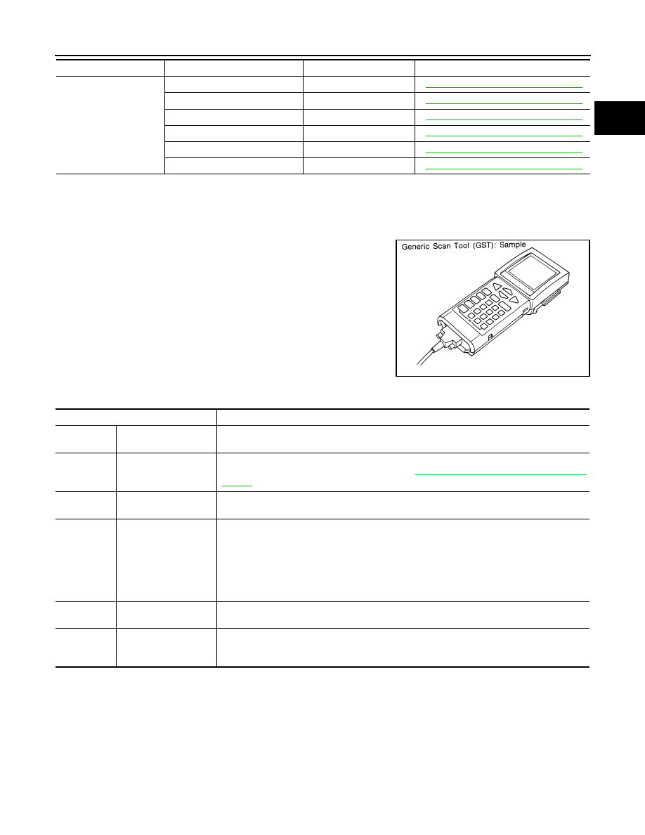
Generic Scan Tool (GST) Function
INFOID:0000000003936478
DESCRIPTION
Generic Scan Tool (OBD II scan tool) complying with SAE J1978 has
several functions explained below.
ISO15765-4 is used as the protocol.
The name GST or Generic Scan Tool is used in this service instruction.
FUNCTION
HO2S2
HO2S2 (B1) P0139
P0139
EC-652, "DTC Confirmation Procedure"
HO2S2 (B1) P1146
P0138
EC-644, "DTC Confirmation Procedure"
HO2S2 (B1) P1147
P0137
EC-639, "DTC Confirmation Procedure"
HO2S2 (B2) P0159
P0159
EC-652, "DTC Confirmation Procedure"
HO2S2 (B2) P1166
P0158
EC-644, "DTC Confirmation Procedure"
HO2S2 (B2) P1167
P0157
EC-639, "DTC Confirmation Procedure"
Test mode
Test item
Corresponding DTC No.
Reference page
SEF139P
Diagnostic test mode
Function
Service $01
READINESS TESTS
This diagnostic service gains access to current emission-related data values, including analog
inputs and outputs, digital inputs and outputs, and system status information.
Service $02
(FREEZE DATA)
This diagnostic service gains access to emission-related data value which were stored by
ECM during the freeze frame. For details, refer to
EC-525, "Emission-related Diagnostic Infor-
Service $03
DTCs
This diagnostic service gains access to emission-related power train trouble codes which
were stored by ECM.
Service $04
CLEAR DIAG INFO
This diagnostic service can clear all emission-related diagnostic information. This includes:
• Clear number of diagnostic trouble codes (Service $01)
• Clear diagnostic trouble codes (Service $03)
• Clear trouble code for freeze frame data (Service $01)
• Clear freeze frame data (Service $02)
• Reset status of system monitoring test (Service $01)
• Clear on board monitoring test results (Service $06 and $07)
Service $06
(ON BOARD TESTS)
This diagnostic service accesses the results of on board diagnostic monitoring tests of specific
components/systems that are not continuously monitored.
Service $07
(ON BOARD TESTS)
This diagnostic service enables the off board test drive to obtain test results for emission-re-
lated powertrain components/systems that are continuously monitored during normal driving
conditions.
2009 Pathfinder
EC-556
< FUNCTION DIAGNOSIS >
[VK56DE]
ON BOARD DIAGNOSTIC (OBD) SYSTEM
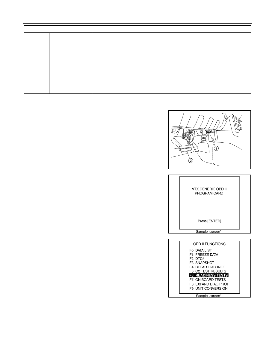
INSPECTION PROCEDURE
1.
Turn ignition switch OFF.
2.
Connect GST to data link connector (1), which is located under
LH dash panel near the hood opener handle.
• Brake pedal (2)
3.
Turn ignition switch ON.
4.
Enter the program according to instructions on the screen or in
the operation instruction.
(*: Regarding GST screens in this section, sample screens are
shown.)
5.
Perform each diagnostic service according to each service pro-
cedure.
For further information, see the GST Operation Instruction of
the tool maker.
Service $08
—
This diagnostic service can close EVAP system in ignition switch ON position (Engine
stopped). When this diagnostic service is performed, the EVAP canister vent control valve can
be closed.
In the following conditions, this diagnostic service cannot function.
• Low ambient temperature
• Low battery voltage
• Engine running
• Ignition switch OFF
• Low fuel temperature
• Too much pressure is applied to EVAP system
Service $09
(CALIBRATION ID)
This diagnostic service enables the off-board test device to request specific vehicle informa-
tion such as Vehicle Identification Number (VIN) and Calibration IDs.
Diagnostic test mode
Function
ALBIA0359ZZ
SEF398S
SEF416S
2009 Pathfinder
TROUBLE DIAGNOSIS - SPECIFICATION VALUE
EC-557
< COMPONENT DIAGNOSIS >
[VK56DE]
C
D
E
F
G
H
I
J
K
L
M
A
EC
N
P
O
COMPONENT DIAGNOSIS
TROUBLE DIAGNOSIS - SPECIFICATION VALUE
Description
INFOID:0000000003936479
The specification (SP) value indicates the tolerance of the value that is displayed in “SPEC” of “DATA MONI-
TOR” mode of CONSULT-III during normal operation of the Engine Control System. When the value in “SPEC”
of “DATA MONITOR” mode is within the SP value, the Engine Control System is confirmed OK. When the
value in “SPEC” of “DATA MONITOR” mode is NOT within the SP value, the Engine Control System may have
one or more malfunctions.
The SP value is used to detect malfunctions that may affect the Engine Control System, but will not illuminate
the MIL.
The SP value will be displayed for the following three items:
• B/FUEL SCHDL (The fuel injection pulse width programmed into ECM prior to any learned on board correc-
tion)
• A/F ALPHA-B1/B2 (The mean value of air-fuel ratio feedback correction factor per cycle)
• MAS A/F SE-B1 (The signal voltage of the mass air flow sensor)
Testing Condition
INFOID:0000000003936480
• Vehicle driven distance: More than 5,000 km (3,107 miles)
• Barometric pressure: 98.3 - 104.3 kPa (1.003 - 1.064 kg/cm
2
, 14.25 - 15.12 psi)
• Atmospheric temperature: 20 - 30
°
C (68 - 86
°
F)
• Engine coolant temperature: 75 - 95
°
C (167 - 203
°
F)
• Engine speed: Idle
• Transmission: Warmed-up
- After the engine is warmed up to normal operating temperature, drive vehicle until “ATF TEMP SE 1” (A/T
fluid temperature sensor signal) indicates more than 60
°
C (140
°
F).
• Electrical load: Not applied
- Rear window defogger switch, air conditioner switch, lighting switch are OFF. Steering wheel is straight
ahead.
Inspection Procedure
INFOID:0000000003936481
NOTE:
Perform “SPEC” in “DATA MONITOR” mode in maximum scale display.
1.
2.
Check that the testing conditions indicated above are met.
3.
Select “B/FUEL SCHDL”, “A/F ALPHA-B1”, “A/F ALPHA-B2” and “MAS A/F SE-B1” in “SPEC” of “DATA
MONITOR” mode with CONSULT-III.
4.
Check that monitor items are within the SP value.
5.
If NG, go to
2009 Pathfinder
Нет комментариевНе стесняйтесь поделиться с нами вашим ценным мнением.
Текст