Nissan Leaf. Instruction — part 683
FRONT DRIVE SHAFT BOOT
FAX-13
< REMOVAL AND INSTALLATION >
C
E
F
G
H
I
J
K
L
M
A
B
FAX
N
O
P
WHEEL SIDE
WHEEL SIDE : Removal and Installation
INFOID:0000000010121663
REMOVAL
1. Remove wheel and tire using power tool. Refer to
2. Remove cotter pin and nut retainer, and then loosen wheel hub lock nut. Refer to
.
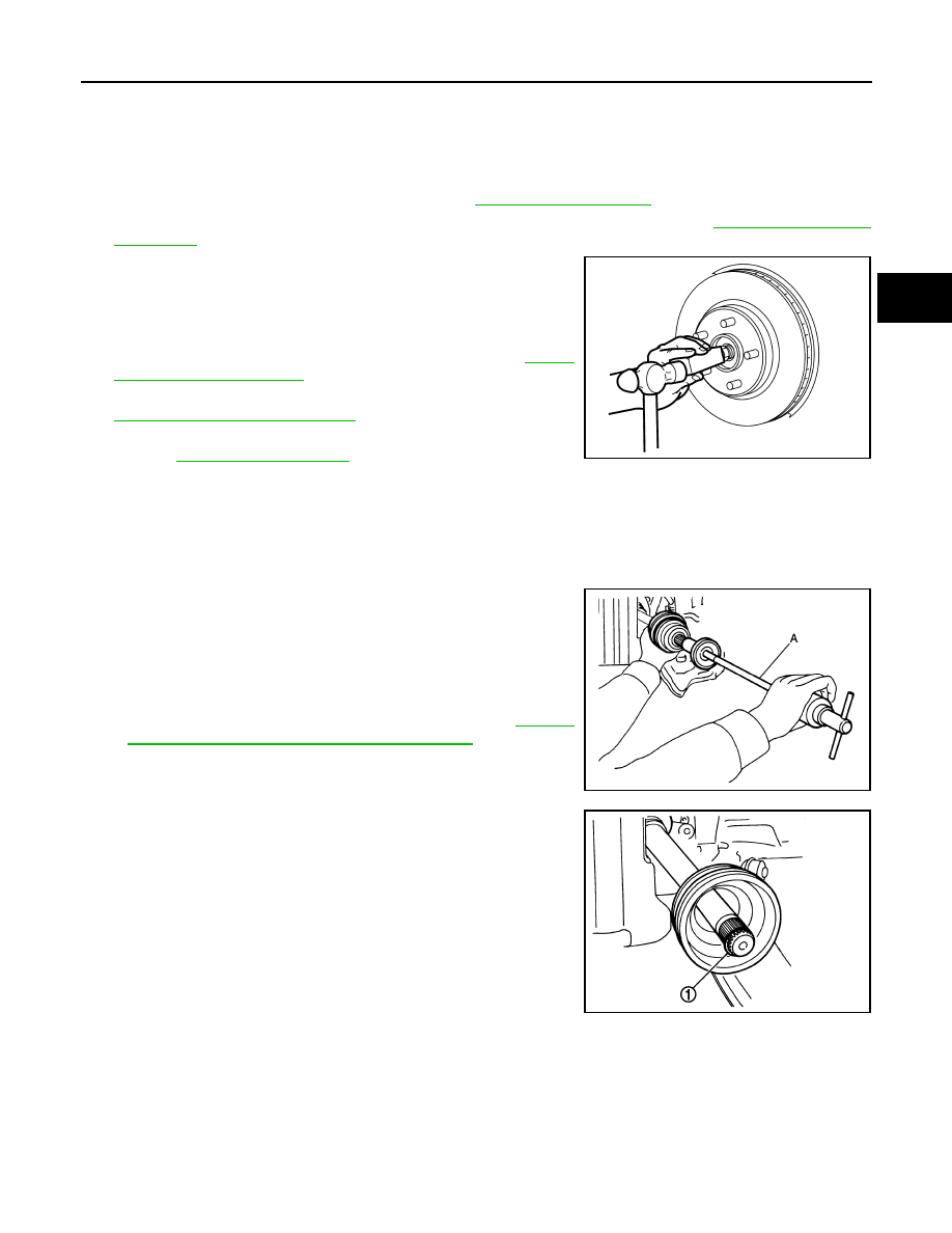
3. Patch wheel hub lock nut with a piece of wood. Hammer the
wood to disengage wheel hub assembly from drive shaft.
NOTE:
Use suitable puller, if wheel hub assembly and drive shaft can-
not be separated even after performing the above procedure.
4. Remove wheel hub lock nut and washer. Refer to
5. Remove steering outer socket from steering knuckle. Refer to
ST-41, "Removal and Installation"
6. Remove transverse link from steering knuckle using power tool.
.
7. Remove drive shaft from wheel hub assembly.
CAUTION:
• Do not place drive shaft joint at an extreme angle. Also be careful not to overextend slide joint.
• Do not allow drive shaft to hang down without support for joint sub-assembly, shaft and the
other parts.
8. Remove boot bands, and then remove boot from joint sub-assembly.
9. Screw suitable tool (A) into joint sub-assembly screw part to a
length of 30 mm (1.18 in) or more. Support drive shaft with one
hand and pull out joint sub-assembly from shaft.
CAUTION:
• Align drive shaft puller and drive shaft and remove them
by pulling firmly and uniformly.
• If joint sub-assembly cannot be pulled out, try after
removing drive shaft from vehicle. Refer to
"WHEEL SIDE : Disassembly and Assembly"
.
10. Remove circular clip (1) from shaft.
11. Remove boot from shaft.
INSTALLATION
1. Clean the old grease on joint sub-assembly with paper waste.
JPDIF0320ZZ
JPDIF0258ZZ
JPDIF0007ZZ
FAX-14
< REMOVAL AND INSTALLATION >
FRONT DRIVE SHAFT BOOT
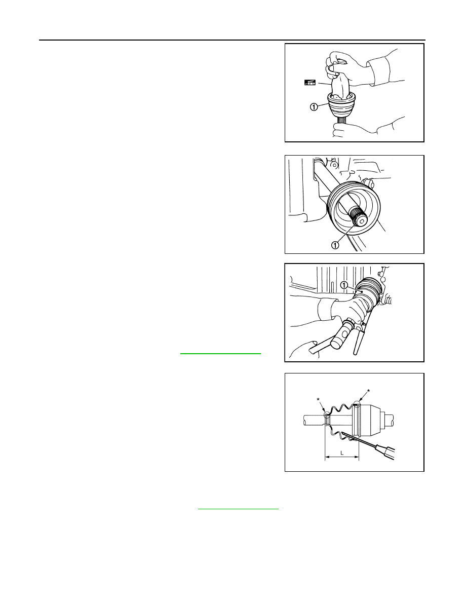
2. Fill serration slot joint sub-assembly (1) with NISSAN genuine
grease or equivalent until the serration slot and ball groove
become full to the brim.
CAUTION:
After applying grease, use a paper waste to wipe off old
grease that has oozed out.
3. Install boot and boot bands to shaft.
CAUTION:
• Wrap serration on shaft with tape to protect the boot from
damage.
• Do not reuse boot and boot band.
4. Remove the tape wrapped around the serration on shaft.
5. Position the circular clip (1) on groove at the shaft edge.
CAUTION:
Do not reuse circular clip.
NOTE:
Drive joint inserter is recommended when installing circular clip.
6. Align both center axles of the shaft edge and joint sub-assembly.
Then assemble shaft with joint sub-assembly holding circular
clip.
7. Install joint sub-assembly (1) to shaft using plastic hammer.
CAUTION:
• Check circular clip is properly positioned on groove of the
joint sub-assembly.
• Confirm that joint sub-assembly is correctly engaged
while rotating drive shaft.
8. Apply the specified amount of grease into the boot inside from
large diameter side of boot.
9. Install the boot securely into grooves (indicated by “*” marks) as
shown.
CAUTION:
If grease adheres to the boot mounting surface (indicated
by “*” marks) on the shaft or joint sub-assembly, boot may
be removed. Remove all grease from the boot mounting
surface.
10. To prevent the deformation of the boot, adjust the boot installa-
tion length to the specified value by inserting the suitable tool
into inside of the boot from the large diameter side of the boot
and discharging the inside air.
CAUTION:
• If the boot installation length exceeds the standard, it may cause breakage of the boot.
• Be careful not to touch the inside of the boot with a tip of tool.
JPDIF0008ZZ
JPDIF0007ZZ
Grease amount
: Refer to
.
JPDIF0011ZZ
(L)
: Boot installation length
Boot installation length : Refer to
.
JSDIA2261ZZ
FRONT DRIVE SHAFT BOOT
FAX-15
< REMOVAL AND INSTALLATION >
C
E
F
G
H
I
J
K
L
M
A
B
FAX
N
O
P
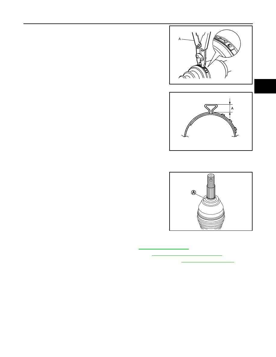
11. Secure the large and small ends of the boot with boot bands
using Tool (A).
CAUTION:
• Do not reuse boot band.
• Secure boot band so that dimension (A) meets the specifi-
cation as shown.
12. Check that displacement does not occur when boot is rotated
with the joint sub-assembly and shaft fixed.
CAUTION:
• Reinstall them using boot bands when boot installation
positions become incorrect.
• Do not reuse boot band.
13. Clean the matching surface of wheel hub lock nut and wheel
hub assembly.
CAUTION:
Do not apply lubricating oil to these matching surface.
14. Clean the matching surface of drive shaft, wheel hub assembly.
And then apply paste [service parts (440037S000)] to surface
(A) of joint sub-assembly of drive shaft.
CAUTION:
Apply paste to cover entire flat surface of joint sub-assem-
bly of drive shaft.
15. Insert drive shaft to wheel hub assembly, install the washer and
then temporarily tighten wheel hub lock nut.
CAUTION:
• Be sure to use torque wrench to tighten the wheel hub lock nut. Do not use a power tool.
• Do not reuse wheel hub lock nut and washer.
16. Install transverse link to steering knuckle. Refer to
17. Install steering outer socket to steering knuckle. Refer to
ST-41, "Removal and Installation"
18. Use the following torque for tightening the wheel hub lock nut. Refer to
CAUTION:
• Since the drive shaft is assembled by press-fitting, use the tightening torque for the wheel hub
lock nut.
• Be sure to use torque wrench to tighten the wheel hub lock nut. Do not use a power tool.
NOTE:
Wheel hub lock nut tightening torque does not over torque for avoiding axle noise, and does not less than
torque for avoiding looseness.
Tool number (A)
: KV40107300 ( — )
JPDIF0012ZZ
(A)
: 7.0 mm (0.276 in) or less.
Amount paste
: 1.0 – 3.0 g (0.04 – 0.10 oz)
JPDIF0268ZZ
JSDIA2844ZZ

FAX-16
< REMOVAL AND INSTALLATION >
FRONT DRIVE SHAFT BOOT
19. When installing a cotter pin (1) and nut retainer (2), securely
bend the basal portion to prevent rattles.
CAUTION:
Do not reuse cotter pin.
20. Install wheel and tire. Refer to
21. Perform inspection after installation. Refer to
REDUCTION GEAR SIDE
REDUCTION GEAR SIDE : Removal and Installation
INFOID:0000000010121664
Remove boot after drive shaft is removed from the vehicle.
• For drive shaft removal and installation, follow the instructions bellow.
- Left side: Refer to
FAX-18, "LEFT SIDE : Removal and Installation"
.
- Right side: Refer to
FAX-19, "RIGHT SIDE : Removal and Installation"
• For drive shaft disassembly and assembly, refer to
FAX-25, "REDUCTION GEAR SIDE : Disassembly and
Inspection
INFOID:0000000010121665
INSPECTION AFTER INSTALLATION
1. Check wheel sensor harness for proper connection. Refer to
BRC-158, "FRONT WHEEL SENSOR :
.
2. Check the wheel alignment. Refer to
3. Adjust neutral position of steering angle sensor. Refer to
.
JPDIF0295ZZ
Нет комментариевНе стесняйтесь поделиться с нами вашим ценным мнением.
Текст