Nissan Leaf. Instruction — part 1177
TM-114
< DTC/CIRCUIT DIAGNOSIS >
[ELECTRIC SHIFT]
U1010 CONTROL UNIT (CAN)
U1010 CONTROL UNIT (CAN)
DTC Logic
INFOID:0000000010119634
DTC DETECTION LOGIC
DTC CONFIRMATION PROCEDURE
1.
PREPARATION BEFORE WORK
If another "DTC CONFIRMATION PROCEDURE" occurs just before, power switch OFF and wait for at least
10 seconds, then perform the next test.
>> GO TO 2.
2.
PERFORM DTC CONFIRMATION PROCEDURE
With CONSULT
1. Power switch OFF to ON and wait for 5 seconds or more.
2. Check DTC.
Is “U1010” detected?
YES
>> Go to
NO-1 >> To check malfunction symptom before repair: Refer to
GI-53, "Intermittent Incident"
.
NO-2 >> Confirmation after repair: INSPECTION END
Diagnosis Procedure
INFOID:0000000010119635
1.
REPLACE VCM
Replace the VCM due to malfunction in the electric shift control module built in VCM. Refer to
.
>> END
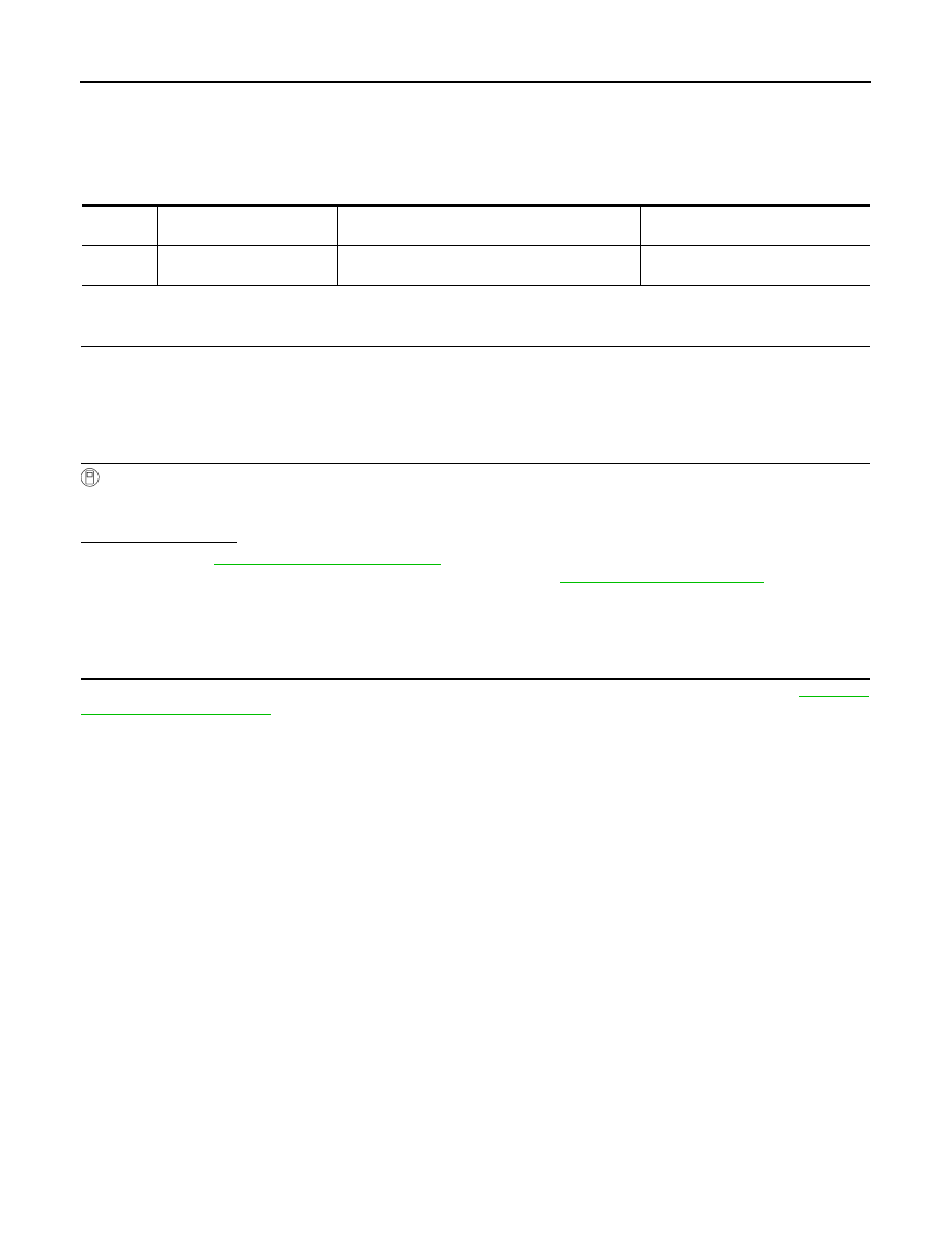
DTC
CONSULT screen terms
(Trouble diagnosis content)
DTC detection condition
Possible cause
U1010
CONTROL UNIT (CAN)
(Control Module Malfunction)
Malfunction is detected in the CAN communication
initial diagnosis (control module malfunction).
Electric shift control module
U1086 CAN ERROR
TM-115
< DTC/CIRCUIT DIAGNOSIS >
[ELECTRIC SHIFT]
C
E
F
G
H
I
J
K
L
M
A
B
TM
N
O
P
U1086 CAN ERROR
DTC Logic
INFOID:0000000010119636
DTC DETECTION LOGIC
DTC DETECTION LOGIC
1.
PREPARATION BEFORE WORK
If another "DTC CONFIRMATION PROCEDURE" occurs just before, power switch OFF and wait for at least
10 seconds, then perform the next test.
>> GO TO 2.
2.
PERFORM DTC CONFIRMATION PROCEDURE
With CONSULT
1. Power switch OFF to ON and wait for 5 seconds or more.
2. Check DTC.
Is “U1086” detected?
YES
>> Go to
NO-1 >> To check malfunction symptom before repair: Refer to
GI-53, "Intermittent Incident"
NO-2 >> Confirmation after repair: INSPECTION END
Diagnosis Procedure
INFOID:0000000010119637
Go to
LAN-17, "Trouble Diagnosis Flow Chart"
.
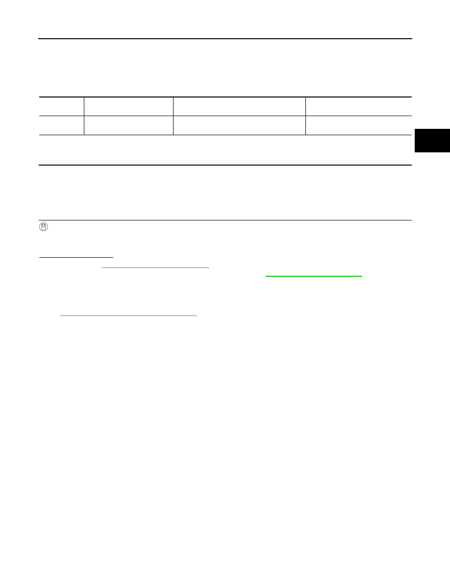
DTC
CONSULT screen terms
(Trouble diagnosis content)
DTC detection condition
Possible cause
U1086
CAN ERROR
(CAN Error)
The inability to transmit or receive data is de-
tected after the power switch is turned OFF.
Electric shift control module
TM-116
< DTC/CIRCUIT DIAGNOSIS >
[ELECTRIC SHIFT]
SELECTOR INDICATOR CIRCUIT
SELECTOR INDICATOR CIRCUIT
Component Function Check
INFOID:0000000010119638
1.
CHECK SELECTOR INDICATOR FUNCTION
1. Set the vehicle to READY.
2. Shift the selector lever.
3. Check that the illuminated position of the selector indicator in the finisher area corresponds to the selected
shift position.
Is the inspection result normal?
YES
>> GO TO 2.
NO
>> Go to
2.
CHECK SELECTOR INDICATOR ILLUMINATION FUNCTION
1. Turn ON the headlamp.
2. Check selector indicator illumination lights up.
Is the inspection result normal?
YES
>> INSPECTION END
NO
>> Go to
Diagnosis Procedure
INFOID:0000000010119639
1.
DETECT MALFUNCTION
Which is malfunctioning part?
Selector indicator illumination>>GO TO 2.
Selector indicator>>GO TO 7.
2.
CHECK SELECTOR INDICATOR ILLUMINATION POWER SUPPLY-1
1. Turn OFF the headlamp.
2. Turn ignition switch OFF.
3. Disconnect selector indicator harness connector.
4. Turn ignition switch ON.
5. Turn ON the headlamp.
6. Check the voltage between selector indicator vehicle side harness connector terminals.
Is the inspection result normal?
YES
>> Check intermittent incident. Refer to
GI-53, "Intermittent Incident"
. If OK, replace selector indica-
tor. Refer to
TM-125, "Removal and Installation"
.
NO
>> GO TO 3.
3.
CHECK SELECTOR INDICATOR ILLUMINATION POWER SUPPLY-2
Check the voltage between selector indicator vehicle side harness connector and ground.
Is the inspection result normal?
YES
>> GO TO 6.
NO
>> GO TO 4.
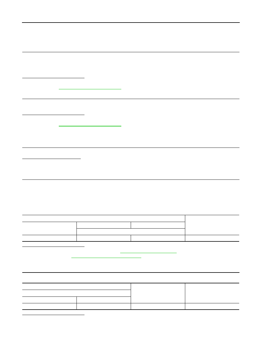
Selector indicator
Voltage
Connector
+
−
Terminal
M56
5
4
9 – 16 V
+
−
Voltage
Selector indicator
Connector
Terminal
M56
5
Ground
9 – 16 V
SELECTOR INDICATOR CIRCUIT
TM-117
< DTC/CIRCUIT DIAGNOSIS >
[ELECTRIC SHIFT]
C
E
F
G
H
I
J
K
L
M
A
B
TM
N
O
P
4.
CHECK FUSE
1. Turn OFF the headlamp.
2. Turn ignition switch OFF.
3. Pull out #46 fuse. Refer to
.)
4. Check that the fuse is not fusing.
Is the inspection result normal?
YES
>> GO TO 5.
NO
>> Replace the fuse after repair the applicable circuit.
5.
CHECK CIRCUIT BETWEEN SELECTOR INDICATOR AND IPDM E/R
1. Disconnect IPDM E/R harness connector.
2. Check the continuity between IPDM E/R vehicle side harness connector and selector indicator vehicle
side harness connector.
3. Also check harness for short to ground.
Is the inspection result normal?
YES
>> Perform IPDM E/R auto active test and check tail lamp relay operation. Refer to
NO
>> Repair or replace damaged parts.
6.
CHECK GROUND CIRCUIT
1. Turn OFF the headlamp.
2. Turn ignition switch OFF.
3. Disconnect combination meter harness connector.
4. Check the continuity between combination meter vehicle side harness connector and selector indicator
vehicle side harness connector.
Is the inspection result normal?
YES
>> Check the combination meter. Refer to
.
NO
>> Repair or replace damaged parts.
7.
CHECK SELECTOR INDICATOR POWER SUPPLY CIRCUIT
1. Disconnect the selector indicator connector.
2. Check the voltage between selector indicator vehicle side harness connector terminal and ground.
Is the inspection result normal?
YES
>> GO TO 9.
NO
>> GO TO 8.
8.
DETECT MALFUNCTION ITEMS
Check the following items.
• 10A fuse (#12) (Refer to
.)
• 12V battery
• Harness for short or open between selector indicator vehicle side harness connector and 12V battery.
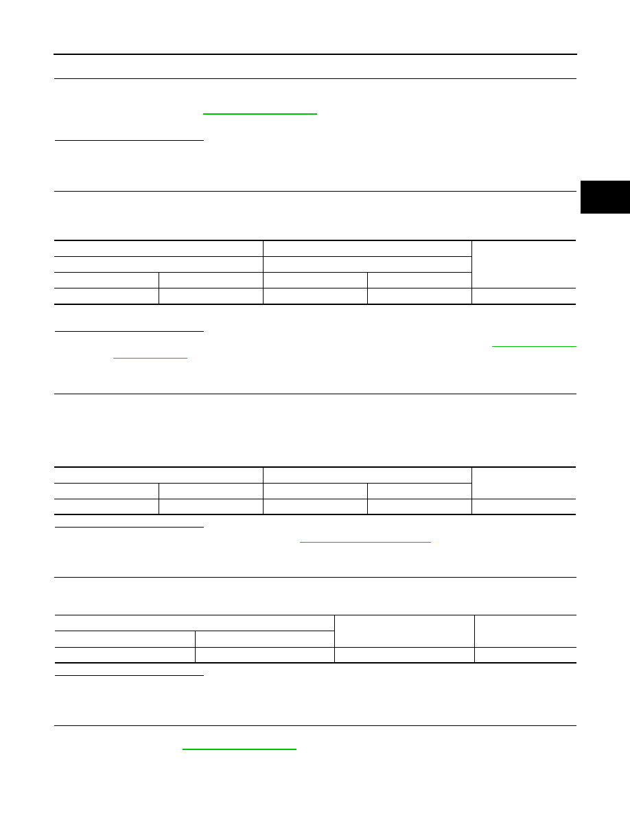
+
−
Continuity
IPDM E/R
Selector indicator
Connector
Terminal
Connector
Terminal
E14
38
M56
5
Existed
Combination meter
Selector indicator
Continuity
Connector
Terminal
Connector
Terminal
M34
26
M56
4
Existed
Selector indicator
Ground
Voltage
Connector
Terminal
M56
2
Ground
9 – 16 V
Нет комментариевНе стесняйтесь поделиться с нами вашим ценным мнением.
Текст