Nissan Leaf. Instruction — part 49

AV
MULTI AV SYSTEM
AV-187
< SYMPTOM DIAGNOSIS >
[AUDIO W/O NAVI (FOR MEXICO)]
C
D
E
F
G
H
I
J
K
L
M
B
A
O
P
SYMPTOM DIAGNOSIS
MULTI AV SYSTEM
Symptom Table
INFOID:0000000010385236
RELATED TO AUDIO
Symptoms
Check items
Probable malfunction location
The disk cannot be removed.
AV control unit
Malfunction in AV control unit.
Refer to
AV-103, "On Board Diagnosis Function"
.
No sound comes out or the level of
the sound is low.
No sound from all speakers.
• Speaker circuit shorted to ground.
• AV control unit power supply and ground circuits
malfunction.
Refer to
AV-173, "AV CONTROL UNIT : Diagnosis
Only a certain speaker (front door
speaker LH, front door speaker RH,
tweeter LH, tweeter RH, rear door
speaker LH, rear door speaker RH does
not output sound.
• Poor connector connection of speaker.
• Sound signal circuit malfunction between AV con-
trol unit and speaker.
Refer to:
-
(front door speak-
er).
-
(tweeter).
-
(rear door speak-
er).
• Malfunction in speaker.
Refer to:
-
AV-194, "Removal and Installation"
(front door
speaker).
-
AV-195, "Removal and Installation"
(tweeter).
-
AV-196, "Removal and Installation"
(rear door
speaker).
• Malfunction in AV control unit.
AV-103, "On Board Diagnosis Function"
.
Noise is mixed with audio.
Noise comes out from all speakers.
• Malfunction in AV control unit.
AV-103, "On Board Diagnosis Function"
.
Noise comes out only from a certain
speaker (front door speaker LH, front
door speaker RH, tweeter LH, tweeter
RH, rear door speaker LH, rear door
speaker RH).
• Poor connector connection of speaker.
• Sound signal circuit malfunction between AV con-
trol unit and speaker.
Refer to:
-
(front door speak-
er).
-
(tweeter).
-
(rear door speak-
er).
• Malfunction in speaker.
• Poor Installation of speaker (e.g. backlash and
looseness).
Refer to:
-
AV-194, "Removal and Installation"
(front door
speaker).
-
AV-195, "Removal and Installation"
(tweeter).
-
AV-196, "Removal and Installation"
(rear door
speaker).
• Malfunction in AV control unit.
AV-103, "On Board Diagnosis Function"
.
Noise is mixed with radio only (when the
vehicle hits a bump or while driving over
bad roads)
Poor connector connection of antenna or antenna
feeder.
Refer to
.
AV-188
< SYMPTOM DIAGNOSIS >
[AUDIO W/O NAVI (FOR MEXICO)]
MULTI AV SYSTEM
RELATED TO HANDS-FREE PHONE
RELATED TO AROUND VIEW MONITOR
No radio reception or poor recep-
tion.
• Other audio sounds are normal.
• Any radio station cannot be received
or poor reception is caused even after
moving to a service area with good re-
ception (e.g. a place with clear view
and no obstacles generating external
noises).
Poor connector connection of antenna or antenna
feeder.
Refer to
.
No satellite radio reception.
There is malfunction in the CONSULT
self diagnosis result.
Refer to
• Malfunction in antenna, antenna feeder or AV con-
trol unit. Perform DTC diagnosis.
Refer to
• Poor continuity in antenna feeder.
• Poor connector connection of antenna or antenna
feeder.
Refer to
There is no malfunction in the CONSULT
self diagnosis result.
Refer to
• Poor continuity in antenna feeder.
• Poor connector connection of antenna or antenna
feeder.
• Loose satellite radio antenna mounting nut.
Refer to
Buzz/rattle sound from speaker
The majority of buzz/rattle sounds are
not indicative of an issue with the speak-
er, usually something nearby the speak-
er is causing the buzz/rattle.
Refer to "SQUEAK AND RATTLE TROUBLE DIAG-
NOSIS" in the appropriate interior trim section.
Symptoms
Check items
Probable malfunction location
Symptoms
Check items
Probable malfunction location
Does not recognize cellular phone
connection (no connection is dis-
played on the display at the guide).
Repeat the registration of cellular phone.
Malfunction in AV control unit.
Replace AV control unit. Refer to
.
Hands-free phone cannot be estab-
lished.
• Hands-free phone operation can be
made, but the communication cannot
be established.
• Hands-free phone operation can be
performed, however, voice between
each other cannot be heard during the
conversation.
The other party’s voice cannot be
heard by hands-free phone.
Check the “microphone speaker” in In-
spection & Adjustment Mode if sound is
heard.
Originating sound is not heard by
the other party with hands-free
phone communication.
Sound operation function is normal.
Sound operation function does not work.
Microphone signal circuit malfunction.
Refer to
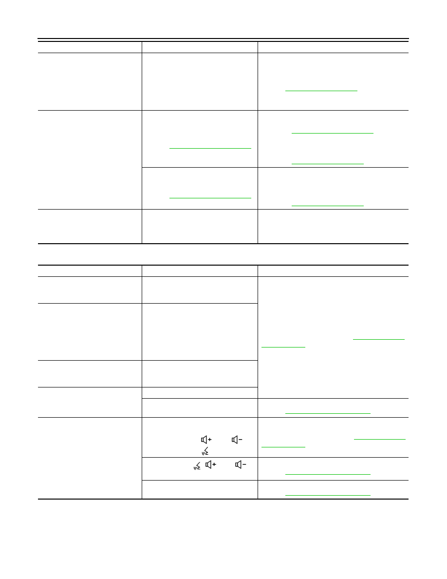
The system cannot be operated.
• The voice recognition can be con-
trolled.
• Steering switch’s
and
switch works, but
does not work.
Steering switch malfunction.
Replace steering switch. Refer to
.
Steering switch’s
,
and
,
switches do not work.
Steering switch signal circuit malfunction.
Refer to
All steering switches do not work.

AV
MULTI AV SYSTEM
AV-189
< SYMPTOM DIAGNOSIS >
[AUDIO W/O NAVI (FOR MEXICO)]
C
D
E
F
G
H
I
J
K
L
M
B
A
O
P
Symptoms
Check items
Probable malfunction location
Display does not switch to camera
image when CAMERA switch is
pressed or selector lever is in R (re-
verse).
Around view monitor control unit mal-
function.
Around view monitor control unit power supply and
ground circuits malfunction.
Refer to
AV-173, "AROUND VIEW MONITOR CON-
TROL UNIT : Diagnosis Procedure"
Camera image signal circuit (output)
malfunction.
Camera image signal circuit (output) malfunction be-
tween around view monitor control unit and AV control
unit.
Refer to
.
Display switches to camera image
when CAMERA switch is pressed or
selector lever is in R (reverse), but
all views are not displayed.
Camera image signal circuit (input) mal-
function.
Camera image signal circuit (input) malfunction be-
tween camera and around view monitor control unit.
Refer to:
•
(front camera).
•
(rear view camera).
•
(side camera LH).
•
(side camera RH).
Camera image is rolling.
Camera image signal circuit (output)
malfunction.
Camera image signal circuit (output) malfunction be-
tween around view monitor control unit and AV control
unit.
Refer to
.
Display does not switch to rear view
monitor even when selector lever is
in R (reverse).
Reverse signal circuit malfunction.
Reverse signal circuit between BCM and around view
monitor control unit.
Refer to
.
Predicted course line display in front
view and rear view is malfunction-
ing.
Steering angle sensor malfunction.
Predictive course line center position is malfunction-
ing.
Refer to
AV-148, "PREDICTIVE COURSE LINE CEN-
TER POSITION ADJUSTMENT : Work Procedure"
.
Front view and front of birds-eye
view is not displayed.
Front camera malfunction.
• Front camera power supply and ground circuits
malfunction.
• Front camera image signal circuit malfunction be-
tween front camera and around view monitor con-
trol unit.
Refer to
.
Front camera image signal circuit mal-
function.
Rear view and rear of birds-eye
view is not displayed.
Rear view camera malfunction.
• Rear view camera power supply and ground cir-
cuits malfunction.
• Rear view camera image signal circuit malfunction
between rear camera and around view monitor con-
trol unit.
Refer to
.
Rear view camera image signal circuit
malfunction.
Front-side and driver side of birds-
eye view is not displayed.
Side camera LH malfunction.
• Side camera LH power supply and ground circuits
malfunction.
• Side camera LH image signal circuit malfunction
between side camera LH and around view monitor
control unit.
Refer to
.
Side camera LH image signal circuit
malfunction.
Front-side and passenger side of
birds-eye view is not displayed.
Side camera RH malfunction.
• Side camera RH power supply and ground circuits
malfunction.
• Side camera RH image signal circuit malfunction
between side camera RH and around view monitor
control unit.
Refer to
.
Side camera RH image signal circuit
malfunction.
Selector lever is in a position other
than R (reverse) and front, rear,
front-side and Birds-Eye views are
displayed even as vehicle speed in-
creases.
Vehicle speed signal malfunction.
Vehicle speed signal malfunction (CAN communica-
tion) between combination meter and around view
monitor control unit.

AV-190
< SYMPTOM DIAGNOSIS >
[AUDIO W/O NAVI (FOR MEXICO)]
NORMAL OPERATING CONDITION
NORMAL OPERATING CONDITION
Description
INFOID:0000000010385237
RELATED TO NOISE
The majority of the audio concerns are the result of outside causes (bad CD, electromagnetic interference,
etc.).
The following noise results from variations in field strength, such as fading noise and multi-path noise, or
external noise from trains and other sources. It is not a malfunction.
• Fading noise: This noise occurs because of variations in the field strength in a narrow range due to moun-
tains or buildings blocking the signal.
• Multi-path noise: This noise results from the waves sent directly from the broadcast station arriving at the
antenna at a different time from the waves which reflect off mountains or buildings.
The vehicle itself can be a source of noise if noise prevention parts or electrical equipment is malfunctioning.
Check if noise is caused and/or changed by engine speed, power switch turned to each position, and opera-
tion of each piece of electrical equipment, and determine the cause.
NOTE:
The source of the noise can be found easily by listening to the noise while removing the fuses of electrical
components, one by one.
Type of Noise and Possible Cause
RELATED TO HANDS-FREE PHONE
Occurrence condition
Possible cause
Occurs only when engine is ON.
A continuous growling noise occurs. The speed of
the noise varies with changes in the engine speed.
• Power components
The occurrence of the noise is linked with the operation of the fuel pump.
• Fuel pump condenser
Noise only occurs when various
electrical components are oper-
ating.
A cracking or snapping sound occurs with the op-
eration of various switches.
• Relay malfunction, AV control unit malfunc-
tion
The noise occurs when various motors are operat-
ing.
• Motor case ground
• Motor
The noise occurs constantly, not just under certain conditions.
• Rear defogger coil malfunction
• Open circuit in printed heater
• Poor ground of antenna feeder line
A cracking or snapping sound occurs while the vehicle is being driven, especially when
it is vibrating excessively.
• Ground wire of body parts
• Ground due to improper part installation
• Wiring connections or a short circuit
Symptom
Cause and Counter measure
Does not recognize cellular phone connection (No connection is
displayed on the display at the guide).
Some Bluetooth
®
enabled cellular phones may not be recognized
by the in-vehicle phone module.
Refer to “RELATED TO HANDS-FREE PHONE (Check Compati-
bility)” in
.
Cannot use hands-free phone.
Customer will not be able to use a hands-free phone under the fol-
lowing conditions:
• The vehicle is outside of the telephone service area.
• The vehicle is in an area where it is difficult to receive radio
waves; such as in a tunnel, in an underground parking garage,
near a tall building or in a mountainous area.
• The cellular phone is locked to prevent it from being dialed.
NOTE:
While a cellular phone is connected through the Bluetooth
®
wire-
less connection, the battery power of the cellular phone may dis-
charge quicker than usual. The Bluetooth
®
Hands-Free Phone
System cannot charge cellular phones.
Нет комментариевНе стесняйтесь поделиться с нами вашим ценным мнением.
Текст