Nissan Leaf. Instruction — part 499

EVC-20
< SYSTEM DESCRIPTION >
COMPONENT PARTS
Stop Lamp Switch
INFOID:0000000010120530
The stop lamp switch is installed to the brake pedal bracket. The
switch detects the state of the brake pedal and transmits an ON/OFF
signal to VCM.
The contact of the stop lamp switch is usually open. When the brake
pedal is depressed, it closes and the stop lamp switch signal is
transmitted as a voltage signal.
ASCD Steering Switch
INFOID:0000000010120531
ASCD steering switch has various values of electrical resistance for
each button. VCM reads voltage variation of switch, and determines
which button is operated.
Brake Pedal Position Switch
INFOID:0000000010120532
The brake pedal position switch is installed to the brake pedal
bracket. The switch detects the state of the brake pedal and trans-
mits an ON/OFF signal to VCM.
The contact of the brake pedal position switch is usually closed.
When the brake pedal is depressed, it opens to disconnect the cir-
cuit, and shut off the output voltage. This constitutes an brake pedal
position switch signal.
Battery Current Sensor (With Battery Temperature Sensor)
INFOID:0000000010120533
BATTERY CURRENT SENSOR
The battery current sensor is installed to the negative cable of the
battery. The battery current sensor detects the battery charge/dis-
charge current and transmits signals to VCM. VCM judges the bat-
tery load based on these signals and controls the power generation
by converting the target generation voltage to a power generation
command signal and transmitting it to the DC/DC converter.
CAUTION:
Never connect the electrical component or the ground wire
directly to the battery terminal. The connection causes the mal-
function of the power voltage variable control, and may cause
the battery to discharge.
BATTERY TEMPERATURE SENSOR
Battery temperature sensor is integrated in battery current sensor.
The sensor measures temperature around the battery.
JSBIA0308ZZ
JSCIA0485ZZ
JSBIA0308ZZ
JPBIA3262ZZ
COMPONENT PARTS
EVC-21
< SYSTEM DESCRIPTION >
D
E
F
G
H
I
J
K
L
M
A
B
EVC
N
O
P
This sensor uses a thermistor and its electrical resistance varies as the temperature varies. VCM detects a
voltage change caused by the change in electrical resistance.
<Reference data>
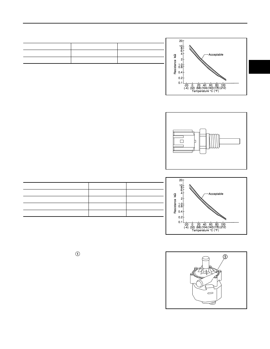
Coolant Temperature Sensor
INFOID:0000000010120534
The coolant temperature sensor is detects the coolant temperature.
This sensor uses a thermistor that changes its electrical resistance
according to the temperature. VCM detects a voltage change
according to electrical resistance change.
<Reference value>
Electric Water Pump
INFOID:0000000010120535
The electric water pump feeds coolant by pressure, which circu-
lates in the high voltage system cooling circuit. They are controlled
by VCM independently so that the amount of pressure feed is
adjusted according to the vehicle speed and water temperature.
The electric water pump also integrates an interface circuit that mon-
itors the pump function for any malfunction, and it transmits a mal-
function signal to VCM if necessary.
Temperature [
°C (°F)]
Voltage (V)
Resistance (k
Ω)
25 (77)
3.333
1.9 - 2.1
90 (194)
0.969
0.222 - 0.258
SEF012P
JSCIA0285ZZ
Coolant temperature [
°C (°F)]
Voltage (V)
Resistance (k
Ω)
–10 (14)
4.4
7.0 - 11.4
20 (68)
3.5
2.35 - 2.73
50 (122)
2.2
0.68 - 1.00
90 (194)
0.9
0.236 - 0.260
SEF012P
JSCIA0046ZZ
EVC-22
< SYSTEM DESCRIPTION >
COMPONENT PARTS
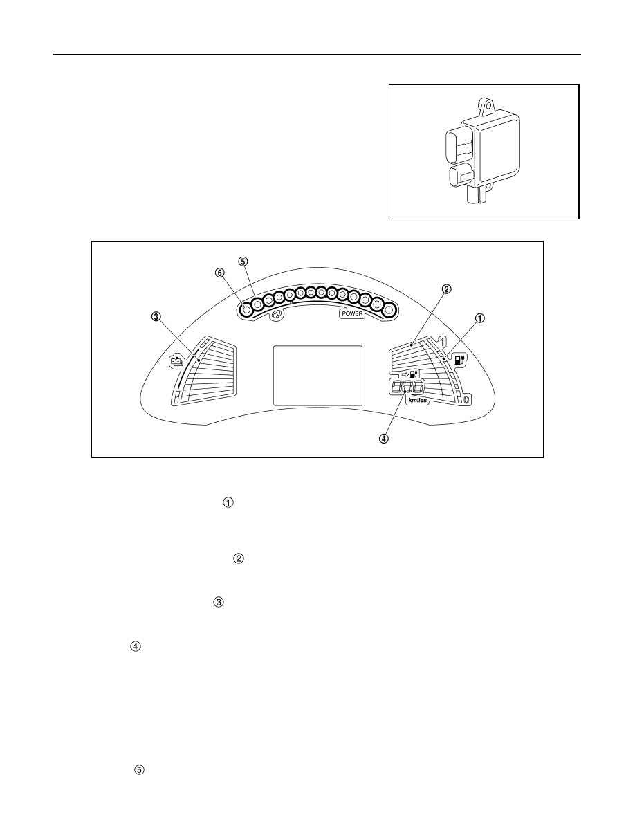
Cooling Fan Control Module
INFOID:0000000010120536
The cooling fan control module is mounted on the cooling fan and
drives the cooling fan motor.
The cooling fan control module conducts communication between
VCM via the PWM communication. The cooling fan control module
drives the cooling fan motor so that the cooling fan speed is con-
trolled in accordance with the control signal from VCM.
Combination Meter
INFOID:0000000010120537
VCM controls the following items on the combination meter.
LI-ION BATTERY INFORMATION
Li-ion Battery Capacity Level Gauge
VCM receives the Li-ion battery capacity signal from the Li-ion battery controller, and VCM transmits the signal
to the combination meter to display the maximum capacity of the Li-ion battery. When the capacity of the Li-ion
battery decreases with age and usage, the level of the gauge is also decreased.
Li-ion Battery Available Charge Gauge
VCM receives the Li-ion battery available charge signal from the Li-ion battery controller, and VCM transmits
the signal to the combination meter to display the available Li-ion battery charge to run the vehicle.
Li-ion Battery Temperature Gauge
VCM receives the Li-ion battery temperature signal from the Li-ion battery controller, and VCM transmits the
signal to the combination meter to display the Li-ion battery temperature.
Distance Range
The driving range (km or miles) provides an estimated distance that the vehicle can be driven before recharg-
ing is necessary. The driving range is constantly being calculated, based on the amount of available Li-ion bat-
tery charge and the actual power consumption average.
VCM calculates average electricity consumption at a specified travel distance, according to total power con-
sumption of the vehicle. Based on the average electricity consumption and the Li-ion battery available charge
signal received from the Li-ion battery, VCM calculates driving range and transmits a driving range signal to
the combination meter.
POWER METER
Maximum Power
JSCIA0081ZZ
JSCIA0068ZZ
COMPONENT PARTS
EVC-23
< SYSTEM DESCRIPTION >
D
E
F
G
H
I
J
K
L
M
A
B
EVC
N
O
P
VCM receives a maximum motor output power signal from the traction motor inverter and a maximum regen-
erative power signal from the Li-ion battery controller. VCM transmits these signals to the combination meter
and displays the upper limit of available output power and regenerative electric power.
Current Motor Power
VCM receives the current motor power signal from the traction motor inverter, and VCM transmits the signal to
the combination meter to display the power currently being output.
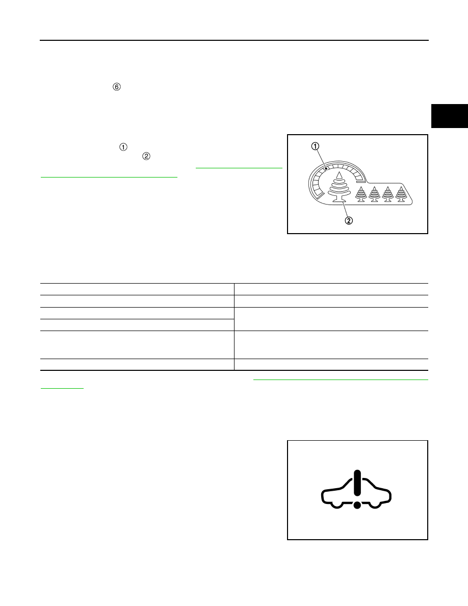
ECO Indicator
INFOID:0000000010120538
The ECO indicator shows the instantaneous ECO drivability in the
instant ECO indicator , and shows the cumulative ECO drivability,
during 1 trip in the ECO tree .
For information regarding control, refer to
TOR CONTROL : System Description"
.
Approaching Vehicle Sound for Pedestrians (VSP)
INFOID:0000000010120539
VSP informs the user of various information by electronic sounds.
In the following cases, VCM transmits a operation signal to VSP.
For details of the charge sound system of VSP, Refer to
VSP-22, "CHARGE SOUND SYSTEM : System
.
WARNING LAMPS/INDICATOR LAMPS
WARNING LAMPS/INDICATOR LAMPS : EV System Warning Lamp
INFOID:0000000010120540
DESIGN/PURPOSE
The EV system warning lamp turns ON if a malfunction occurs with
the EV system.
BULB CHECK
For approximately 2 seconds after the power switch is turned ON.
SYNCHRONIZATION WITH MASTER WARNING LAMP
JSCIA0067ZZ
Condition
Operation status
EVSE is connected to the normal charge port
Short beep (once)
When normal charging starts
Short beeps in sequence (twice)
When timer charge goes into standby mode
Press the charge port lid opener switch or the charge port lid open-
er button of intelligent key
(Hazard and buzzer reminder)
Three short beeps
When EVSE is not connected correctly
Three short beeps continue repeatedly for 30 seconds
JSCIA0026ZZ
Нет комментариевНе стесняйтесь поделиться с нами вашим ценным мнением.
Текст