Nissan Leaf. Instruction — part 9
AV
DIAGNOSIS SYSTEM (BLUETOOTH® CONTROL UNIT)
AV-27
< SYSTEM DESCRIPTION >
[AUDIO W/O NAVI (EXCEPT MEXICO)]
C
D
E
F
G
H
I
J
K
L
M
B
A
O
P
DIAGNOSIS SYSTEM (BLUETOOTH® CONTROL UNIT)
Diagnosis Description
INFOID:0000000010122471
The Bluetooth
®
control unit has two diagnostic checks. The first diagnostic check is performed automatically
every power cycle during control unit initialization. The second diagnostic check is performed by the technician
using the steering wheel audio control switches prior to trouble diagnosis.
Bluetooth
®
CONTROL UNIT INITIALIZATION CHECKS
• Internal control unit failure
• Bluetooth
®
antenna connection open or shorted
• Steering wheel audio control switches [
(PHONE/SEND), (PHONE/END)] stuck closed
• Vehicle speed pulse count
• Microphone connection test (with playback to operator)
• Bluetooth
®
inquiry check
OPERATION PROCEDURE
1. Turn power switch to ACC or ON.
2. Wait for the Bluetooth
®
system to complete initialization. This may take up to 20 seconds.
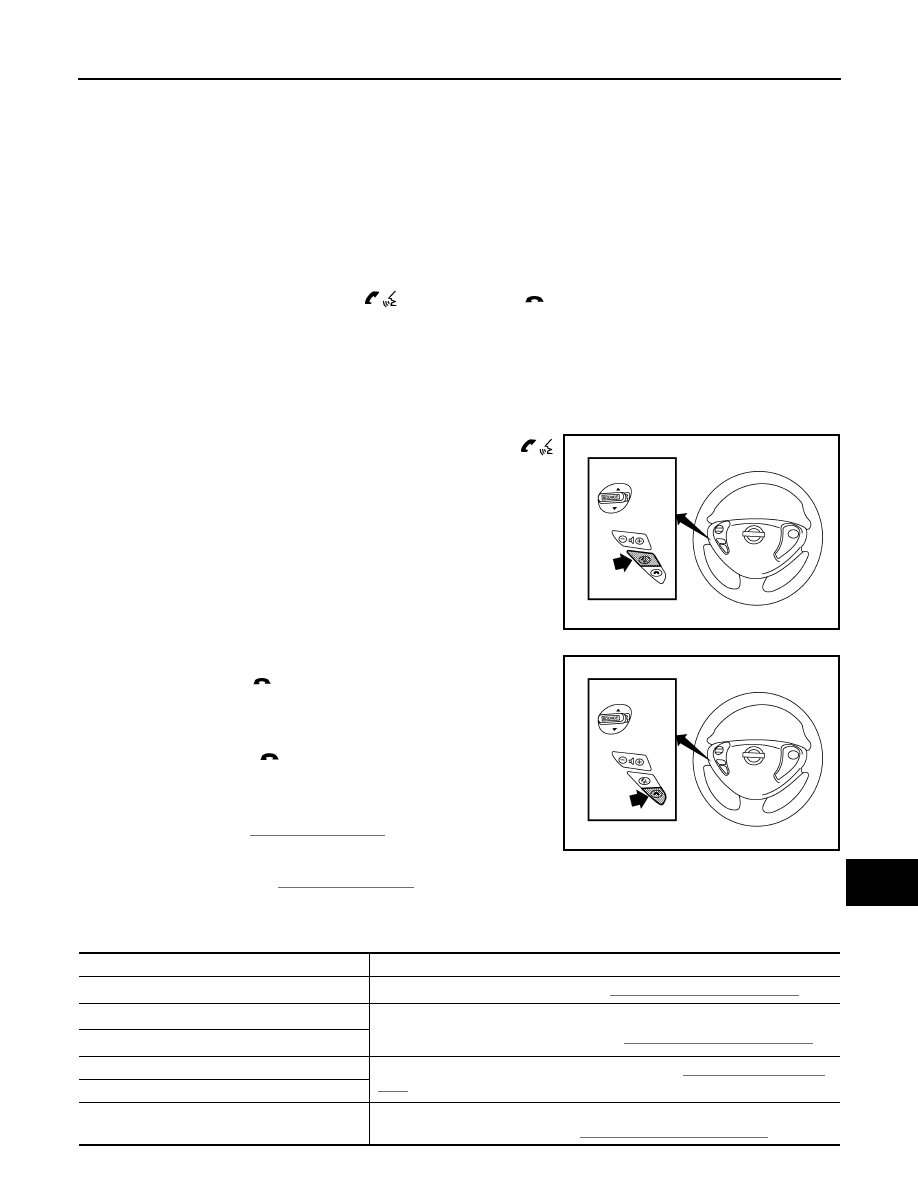
3. Press and hold the steering wheel audio control switch
(PHONE/SEND) button for at least 5 seconds. The Bluetooth
®
system will begin to play a verbal prompt.
4. While the prompt is playing, press and hold the steering wheel
audio control switch (PHONE/END) button until you hear the
“Diagnostics mode” prompt. The Bluetooth
®
system will sound a
5-second beep.
5. While the beep is sounding, press and hold the steering wheel
audio control switch
(PHONE/END) button again until you
hear prompts.
6. The Bluetooth
®
system has now entered into the diagnostic
mode. Results of the diagnostic checks will be verbalized to the
technician. Refer to
7. After the failure records are reported, an interactive microphone
test will be performed. Follow the voice prompt. If the micro-
phone test fails, refer to
Work Flow
INFOID:0000000010122472
AWNIA3008ZZ
AWNIA3009ZZ
Failure Message
Action
“Internal failure”
Replace Bluetooth
®
control unit. Refer to
AV-73, "Removal and Installation"
.
“Bluetooth
®
antenna open”
1.
Inspect harness connection.
2.
Replace Bluetooth
®
antenna. Refer to
AV-73, "Removal and Installation"
“Bluetooth
®
antenna shorted”
“Phone/Send for Hands Free System is stuck”
Check steering wheel audio control switches. Refer to
“Phone/End for the Hands Free System is stuck”
“Microphone test” (failed interactive test)
1.
Inspect harness between Bluetooth
®
control unit and microphone.
2.
Replace microphone. Refer to
AV-72, "Removal and Installation"
.
AV-28
< ECU DIAGNOSIS INFORMATION >
[AUDIO W/O NAVI (EXCEPT MEXICO)]
AUDIO UNIT
ECU DIAGNOSIS INFORMATION
AUDIO UNIT
Reference Value
INFOID:0000000010122473
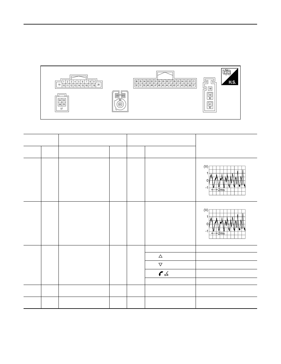
TERMINAL LAYOUT
PHYSICAL VALUES
AWNIA3453ZZ
Terminal
(Wire color)
Description
Condition
Reference value
(Approx.)
+
–
Signal name
Input/
Output
Power
switch
Operation
2
(L)
3
(P)
Sound signal front speaker
LH
Output
ON
Sound output
4
(V)
5
(LG)
Sound signal rear speaker
LH
Output
ON
Sound output
6
(BR)
15
(SB)
Steering switch signal A
Input
ON
Press SOURCE switch
0V
Press
switch
1.0V
Press
switch
2.0V
Press
switch
3.0V
Except above
5.0V
7
(BR)
Ground ACC power supply
Input
ACC
—
Battery voltage
9
(W)
8
(B)
Illumination control signal
Input
ON
Headlamps ON
Battery voltage
SKIB3609E
SKIB3609E
AV
AUDIO UNIT
AV-29
< ECU DIAGNOSIS INFORMATION >
[AUDIO W/O NAVI (EXCEPT MEXICO)]
C
D
E
F
G
H
I
J
K
L
M
B
A
O
P
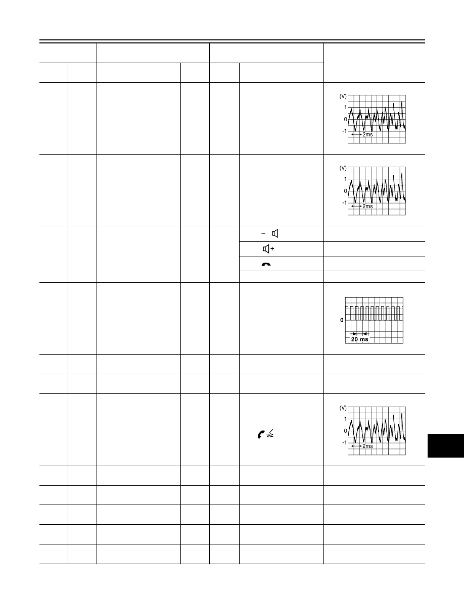
11
(G)
12
(R)
Sound signal front speaker
RH
Output
ON
Sound output
13
(LG)
14
(P)
Sound signal rear speaker
RH
Output
ON
Sound output
16
(V)
15
(SB)
Steering switch signal B
Input
ON
Press
switch
0V
Press
switch
1.0V
Press
switch
2.0V
Except above
5.0V
18
(GR)
Ground Vehicle speed signal
Input
ON
When vehicle speed is ap-
prox. 40 km/h (25 MPH)
19
(BR)
Ground Battery power supply
Input
OFF
—
Battery voltage
20
(B)
Ground Ground
—
ON
—
0 V
24
(R)
25
(G)
TEL voice signal
Input
ON
During voice guide output
with
switch pressed.
26
(Shield)
—
TEL voice signal shield
—
—
—
—
31
(R)
—
AV communication (H)
Input/
Output
—
—
—
32
(G)
—
AV communication (L)
Input/
Output
—
—
—
33
(B)
Ground Camera ground
—
ON
—
0 V
34
(W)
Ground Camera power supply
Output
ON
Selector lever in “R” posi-
tion
6.0 V
Terminal
(Wire color)
Description
Condition
Reference value
(Approx.)
+
–
Signal name
Input/
Output
Power
switch
Operation
SKIB3609E
SKIB3609E
JSNIA0012GB
SKIB3609E

AV-30
< ECU DIAGNOSIS INFORMATION >
[AUDIO W/O NAVI (EXCEPT MEXICO)]
AUDIO UNIT
35
(R)
Ground Camera image signal
Input
ON
Camera image displayed
36
(Shield)
—
Camera image signal
Shield
—
—
—
—
44
(B)
Ground Camera detection
—
ON
—
0 V
45
(B)
Ground EQ1 Ground
—
ON
—
0 V
48
(B)
Ground EQ4 Ground
—
ON
—
0 V
50
(G)
Ground Reverse signal
Input
ON
Selector lever in R position.
Battery voltage
Selector lever in any posi-
tion other than R.
0 V
53
(W)
—
V BUS signal
—
—
—
—
54
(G)
—
USB ground
—
—
—
—
55
(L)
—
USB D+ signal
—
—
—
—
56
(R)
—
USB D
− signal
—
—
—
—
57
(Shield)
—
USB signal shield
—
—
—
—
58
(B)
Ground Antenna amp. ON signal
Output
ON
—
Battery voltage
59
(B)
Ground AM/FM antenna signal
Input
ON
—
5.0 V
60
(Shield)
—
AM/FM antenna signal
shield
—
—
—
—
63
(B)
Ground Satellite antenna signal
Input
ON
—
5.0 V
64
(Shield)
—
Satellite antenna signal
shield
—
—
—
—
Terminal
(Wire color)
Description
Condition
Reference value
(Approx.)
+
–
Signal name
Input/
Output
Power
switch
Operation
SKIB2251J
Нет комментариевНе стесняйтесь поделиться с нами вашим ценным мнением.
Текст