Nissan Leaf. Instruction — part 154
BCS-10
< SYSTEM DESCRIPTION >
SYSTEM
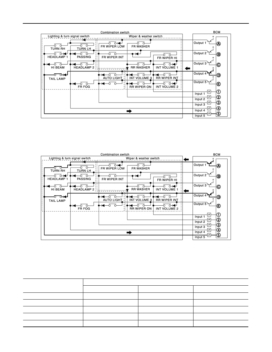
• The circuit between OUTPUT 4 and INPUT 5 is formed when the TAIL LAMP switch is turned ON.
• BCM detects the combination switch status signal “5D” when the signal of OUTPUT 4 is input to INPUT 5.
• BCM judges that the TAIL LAMP switch is ON when the signal “5D” is detected.
Example 2: When some switches (TURN RH switch, TAIL LAMP switch) are turned ON
• The circuits between OUTPUT 1 and INPUT 5 and between OUTPUT 4 and INPUT 5 are formed when the
TURN RH switch and TAIL LAMP switch are turned ON.
• BCM detects the combination switch status signal “5AD” when the signals of OUTPUT 1 and OUTPUT 4 are
input to INPUT 5.
• BCM judges that the TURN RH switch and TAIL LAMP switch are ON when the signal “5AD” is detected.
WIPER VOLUME DIAL POSITION
BCM judges the wiper volume dial 1 - 7 by the status of INT VOLUME 1, 2 and 3 switches.
JPMIA1545GB
JPMIA1546GB
Wiper intermittent
dial position
Switch status
INT VOLUME 1
INT VOLUME 2
INT VOLUME 3
1
ON
ON
ON
2
ON
ON
OFF
3
ON
OFF
OFF
4
OFF
OFF
OFF
5
OFF
OFF
ON
BCS
SYSTEM
BCS-11
< SYSTEM DESCRIPTION >
C
D
E
F
G
H
I
J
K
L
B
A
O
P
N
NOTE:
For details of wiper volume dial position, refer to
WW-8, "FRONT WIPER AND WASHER SYSTEM : System Description"
.
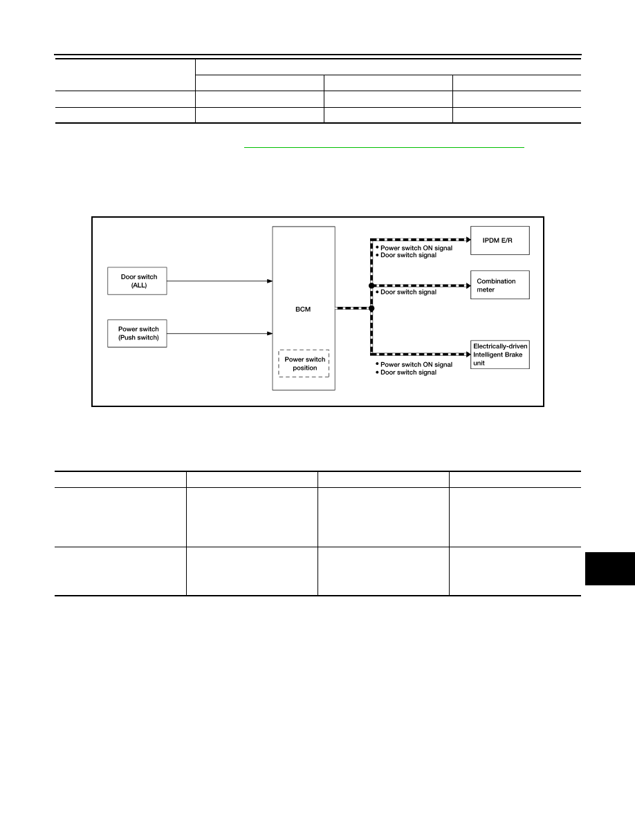
SIGNAL BUFFER SYSTEM
SIGNAL BUFFER SYSTEM : System Description
INFOID:0000000010122305
SYSTEM DIAGRAM
OUTLINE
BCM has the signal transmission function that outputs/transmits each input/received signal to each unit.
Signal transmission function list
POWER CONSUMPTION CONTROL SYSTEM
6
OFF
ON
ON
7
OFF
ON
OFF
Wiper intermittent
dial position
Switch status
INT VOLUME 1
INT VOLUME 2
INT VOLUME 3
AWMIA1404GB
Signal name
Input
Output
Description
Power switch ON signal
Power switch (push switch)
• IPDM E/R (CAN)
• Electrically-driven Intelligent
Brake unit (CAN)
Inputs the power switch (push
switch) signal and transmits the
power switch position status
judged with BCM via CAN com-
munication.
Door switch signal
Any door switch
• Combination meter (CAN)
• IPDM E/R (CAN)
• Electrically-driven Intelligent
Brake unit (CAN)
Inputs the door switch signal
and transmits it via CAN com-
munication.
BCS-12
< SYSTEM DESCRIPTION >
SYSTEM
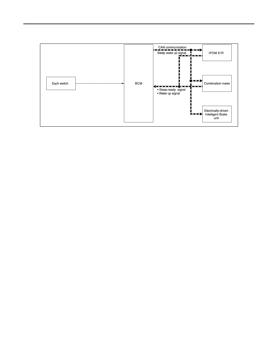
POWER CONSUMPTION CONTROL SYSTEM : System Description
INFOID:0000000010122306
SYSTEM DIAGRAM
OUTLINE
• BCM incorporates a power saving control function that reduces the power consumption according to the
vehicle status.
• BCM switches the status (control mode) by itself with the power saving control function. It performs the sleep
request to each unit (IPDM E/R, combination meter and Electrically-driven Intelligent Brake unit) that oper-
ates with the power switch OFF.
Normal mode (wake-up)
- CAN communication is normally performed with other units
- Each control with BCM is operating properly
CAN communication sleep mode (CAN sleep)
- CAN transmission is stopped
- Control with BCM only is operating
Low power consumption mode (BCM sleep)
- Low power consumption control is active
- CAN transmission is stopped
LOW POWER CONSUMPTION CONTROL WITH BCM
BCM reduces the power consumption with the following operation in the low power consumption mode.
• The reading interval of the each switches changes from 10 ms interval to 60 ms interval.
Sleep mode activation
• BCM receives the sleep-ready signal (ready) from IPDM E/R and combination meter via CAN communica-
tion.
• BCM transmits the sleep wake up signal (sleep) to each unit when all of the CAN sleep conditions are ful-
filled.
• Each unit stops the transmission of CAN communication with the sleep wake up signal. BCM is in CAN com-
munication sleep mode.
• BCM is in the low power consumption mode and perform the low power consumption control when all of the
BCM sleep conditions are fulfilled with CAN sleep condition.
JMMIA0613GB

BCS
SYSTEM
BCS-13
< SYSTEM DESCRIPTION >
C
D
E
F
G
H
I
J
K
L
B
A
O
P
N
Sleep condition
INL-10, "INTERIOR ROOM LAMP BATTERY SAVER SYSTEM : System Description"
for details of the interior room lamp bat-
tery saver time.
Wake-up operation
• BCM transmits sleep wake up signal (wake up) to each unit when any condition listed below is established,
and then goes into normal mode from low power consumption mode.
• Each unit starts transmissions with CAN communication by receiving sleep wake up signals. Each unit trans-
mit wake up signals to BCM with CAN communication to convey the start of CAN communication.
Wake-up condition
CAN sleep condition
BCM sleep condition
• Receiving the sleep-ready signal (ready) from all units
• 1 minute after turning power switch OFF
• Theft warning alarm and panic alarm: Not operation
• Warning chime: Not operation
• Intelligent Key system buzzer: Not operation
• Stop lamp switch: OFF
• Turn signal indicator lamp: Not operation
• Exterior lamp: OFF
• Door lock status: No change
• CONSULT communication status: Not communication
• Meter display signal: Non-transmission
• Door switch status: No change
• Driver door lock status: No change
• Interior room lamp battery saver: Time out*
• RAP system: Not operation
• Nissan Vehicle Immobilizer System (NVIS) - NATS: Not opera-
tion
• Remote keyless entry receiver communication status: No com-
munication
• Tire pressurer monitoring system (TPMS): Stop
• ACC/ON indicator lamp: Not operation
Wake-up condition
• Receiving the sleep-ready signal (Not-ready) from any units
• Power switch (push switch): OFF
→ ON
• Hazard switch: ON
• HI BEAM switch: OFF
→ ON, ON → OFF
• PASSING switch: OFF
→ ON, ON → OFF
• HEADLAMP 1 switch: OFF
→ ON, ON → OFF
• HEADLAMP 2 switch: OFF
→ ON, ON → OFF
• TAIL LAMP switch: OFF
→ ON
• FR FOG switch: OFF
→ ON, ON → OFF
• TURN RH: OFF
→ ON, ON → OFF
• TURN LH: OFF
→ ON, ON → OFF
• Driver door switch: OFF
→ ON, ON → OFF
• Passenger door switch: OFF
→ ON, ON → OFF
• Rear RH door switch: OFF
→ ON, ON → OFF
• Rear LH door switch: OFF
→ ON, ON → OFF
• Back door switch: OFF
→ ON, ON → OFF
• Driver door request switch: OFF
→ ON
• Passenger door request switch: OFF
→ ON
• Back door request switch: OFF
→ ON
• Back door opener switch: OFF
→ ON
• Stop lamp switch: ON
• Door lock and unlock switch: NEUTRAL
→ LOCK, NEUTRAL → UNLOCK
• Front door lock assembly (driver side) (door key cylinder switch): NEUTRAL
→ LOCK, NEUTRAL → UNLOCK
• Remote keyless entry receiver communication: Receiving
• Front door lock assembly (driver side) (unlock sensor): OFF
→ ON, ON → OFF
Нет комментариевНе стесняйтесь поделиться с нами вашим ценным мнением.
Текст