Subaru Impreza 3 / Impreza WRX / Impreza WRX STI. Service manual — part 485

TPM(diag)-17
Tire Pressure Warning Light / Trouble Indicator Light Illumination Pattern
TIRE PRESSURE MONITORING SYSTEM (DIAGNOSTICS)
C: TIRE PRESSURE WARNING LIGHT DOES NOT COME OFF
DETECTING CONDITION:
• Defective combination meter
• Tires pressure drop
• Transmitter ID not registered
TROUBLE SYMPTOM:
Tire pressure warning light remains illuminating after engine starts.
Step
Check
Yes
No
1
Is a DTC displayed?
2
CHECK TRANSMITTER (ID).
Display the transmitter ID of the tire pressure
monitor system.
Is the transmitter ID registered? Go to step
3
CHECK TRANSMITTER DATA OUTPUT.
1) Select data display of the tire pressure mon-
itoring.
2) Start the engine and check the tire pressure
warning light output.
Is the warning light output ON? Replace the TPMS
Replace the com-
bination meter.
<Ref. to IDI-16,
REMOVAL, Com-
bination Meter.>
TPM(diag)-18
Tire Pressure Warning Light / Trouble Indicator Light Illumination Pattern
TIRE PRESSURE MONITORING SYSTEM (DIAGNOSTICS)
D: TIRE PRESSURE WARNING LIGHT IS 25 TIMES BLINKING AND TURN ON
DETECTING CONDITION:
• Defective TPMS & keyless entry control module
• Defective harness
• Transmitter is faulty.
TROUBLE SYMPTOM:
Every time the engine starts, tire pressure warning light blinks 25 times and then illuminates.
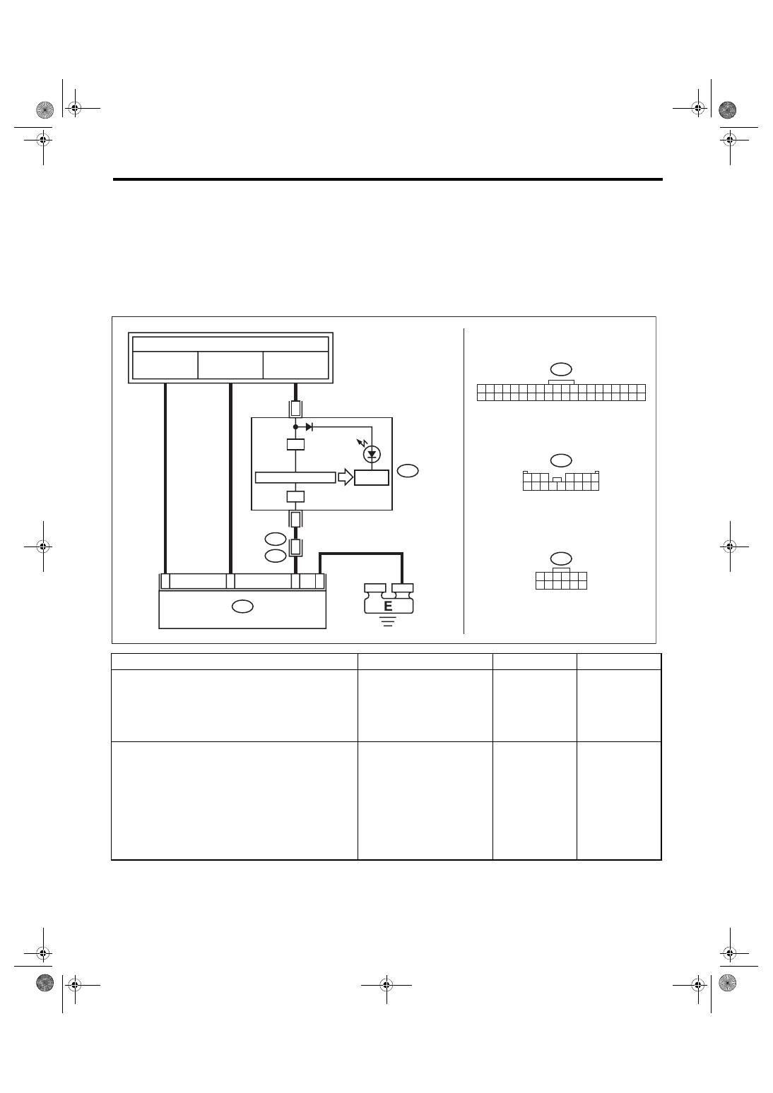
WIRING DIAGRAM:
Tire Pressure Monitoring System <Ref. to WI-71, WIRING DIAGRAM, Tire Pressure Monitoring System.>
Step
Check
Yes
No
1
Is diagnostics code (DTC) dis-
played?
2
CHECK HARNESS.
1) Connect the Subaru Select Monitor to the
terminal No. 2 of the TPMS & keyless entry con-
trol module connector (R221).
Connector & terminal
(R221) No. 2 (+) — Chassis ground (–):
2) Turn the ignition switch to ON, and select
“Oscilloscope” from the Main Menu of Subaru
Select Monitor.
3) Check the voltage displayed.
Is the voltage 10 V or more?
I/F
I/F
R221
1 2 3 4 5 6
7 8 9 10 11 12
1 2 3
4 5 6 7
8 9 10 11 12 13 14 15 16
i102
i10
1 2 3 4 5 6 7 8 9 10 11 12 13 14 15 16 17 18 19 20
21 22 23 24 25 26 27 28 29 30 31 32 33 34 35 36 37 38 39 40
i102
R167
15
R221
TPM00079
34
i10
2
5
2
4
6
TO POWER SUPPLY CIRCUIT
FB-36
F/B FUSE NO. 5
(IG)
FB-48
F/B FUSE NO. 4
(IG)
FB-11
M/B FUSE NO. 8
(B)
COMBINATION
METER
DRIVE
CIRCUIT
MICRO COMPUTER
TIRE INFLATION
PRESSURE
WARNING LIGHT
TPMS & KEYLESS ENTRY CM
TPM(diag)-19
Tire Pressure Warning Light / Trouble Indicator Light Illumination Pattern
TIRE PRESSURE MONITORING SYSTEM (DIAGNOSTICS)
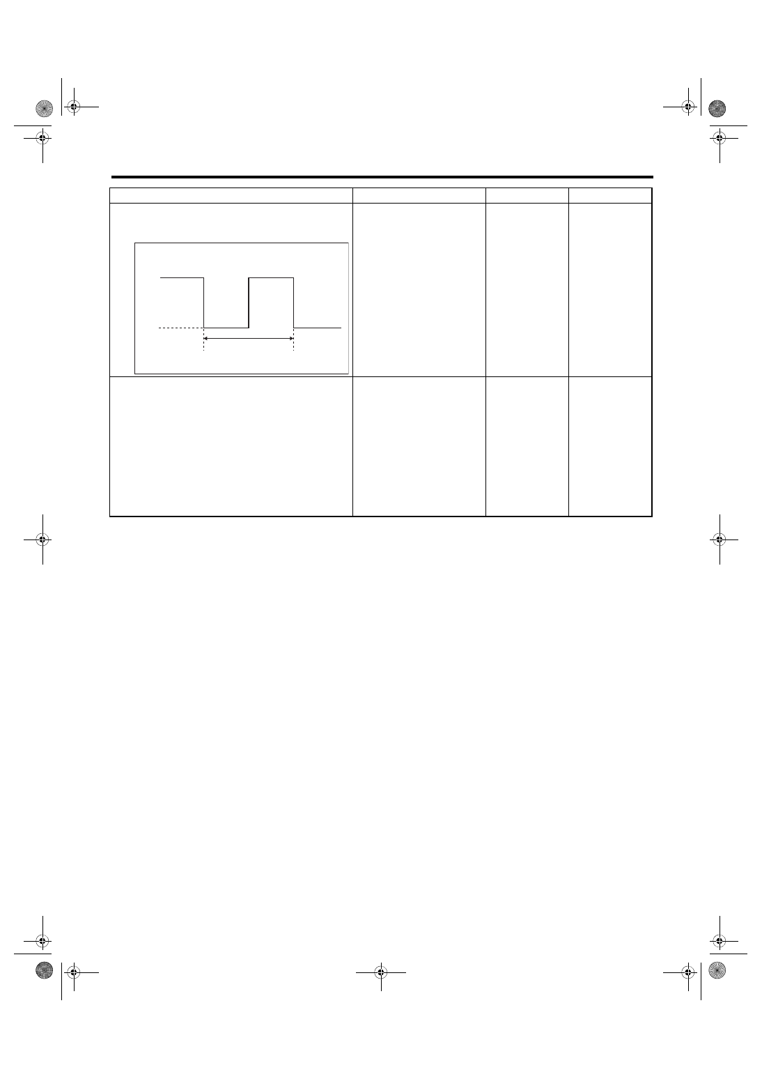
3
CHECK HARNESS.
1) Check the output waveform displayed in the
oscilloscope of Subaru Select Monitor.
Is the pattern the same output
waveform as shown in the fig-
ure?
(1) 400±9 ms Duty 50%
High: Battery voltage
Low: 1.5 V or less
Check the combi-
nation meter. <Ref.
to IDI-5, INSPEC-
TION, Combina-
tion Meter
System.>
4
CHECK HARNESS.
1) Disconnect the TPMS & keyless entry con-
trol module connector.
2) Connect the Subaru Select Monitor to the
terminal No. 2 of the TPMS & keyless entry con-
trol module connector (R221).
Connector & terminal
(R221) No. 2 (+) — Chassis ground (–):
3) Turn the ignition switch to ON, and select
“Oscilloscope” from the Main Menu of Subaru
Select Monitor.
4) Check the voltage displayed.
Is the voltage 10 V or more?
The harness
between the com-
bination meter
connector and the
TPMS & keyless
entry control mod-
ule connector is
shorted or open.
Repair or replace
the harness.
Step
Check
Yes
No
TPM00044
High
Low
(1)
TPM(diag)-20
List of Diagnostic Trouble Code (DTC)
TIRE PRESSURE MONITORING SYSTEM (DIAGNOSTICS)
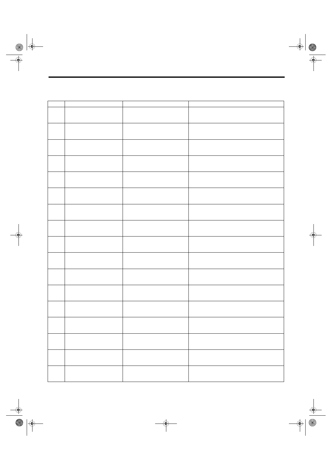
10.List of Diagnostic Trouble Code (DTC)
A: LIST
DTC
Item
Contents of diagnosis
Remarks
11
Tire 1 Air Pressure Decrease
Tire pressure of tire 1 is reduced.
12
Tire 2 Air Pressure Decrease
Tire pressure of tire 2 is reduced.
13
Tire 3 Air Pressure Decrease
Tire pressure of tire 3 is reduced.
14
Tire 4 Air Pressure Decrease
Tire pressure of tire 4 is reduced.
21
Transmitter 1 No Data
Data cannot be received from
transmitter 1.
22
Transmitter 2 No Data
Data cannot be received from
transmitter 2.
23
Transmitter 3 No Data
Data cannot be received from
transmitter 3.
24
Transmitter 4 No Data
Data cannot be received from
transmitter 4.
31
Transmitter 1 Pressure Data
Abnormal
Transmitter 1 data contents are
abnormal.
32
Transmitter 2 Pressure Data
Abnormal
Transmitter 2 data contents are
abnormal.
33
Transmitter 3 Pressure Data
Abnormal
Transmitter 3 data contents are
abnormal.
34
Transmitter 4 Pressure Data
Abnormal
Transmitter 4 data contents are
abnormal.
41
Transmitter 1 Function Code
Abnormal
Function code has error.
42
Transmitter 2 Function Code
Abnormal
Function code has error.
43
Transmitter 3 Function Code
Abnormal
Function code has error.
44
Transmitter 4 Function Code
Abnormal
Function code has error.
51
Transmitter 1 Battery Voltage
Decrease
Transmitter battery voltage is low.
Нет комментариевНе стесняйтесь поделиться с нами вашим ценным мнением.
Текст