Subaru Impreza 3 / Impreza WRX / Impreza WRX STI. Service manual — part 76
ME(STI)-66
Camshaft
MECHANICAL
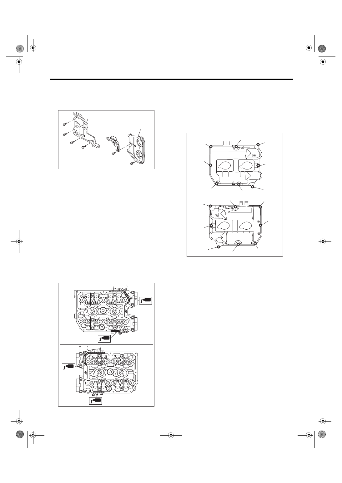
6) Install the timing belt cover No. 2 RH (A) and tim-
ing belt cover No. 2 LH (B).
Tightening torque:
5 N·m (0.5 kgf-m, 3.7 ft-lb)
7) Install the cam sprocket. <Ref. to ME(STI)-59,
8) Install the timing belt. <Ref. to ME(STI)-52, IN-
9) Adjust the valve clearance. <Ref. to ME(STI)-29,
10) Install the rocker cover.
(1) Install the rocker cover gasket to the rocker
cover. (outer section and ignition coil section)
NOTE:
Use a new rocker cover gasket.
(2) Apply liquid gasket to the specified point of
the cylinder head.
NOTE:
Install within 5 min. after applying liquid gasket.
Liquid gasket:
THREE BOND 1217G (Part No. K0877Y0100)
or equivalent
(3) Install the rocker cover onto cylinder heads.
Ensure the gasket is properly positioned during
installation.
(4) Temporarily tighten the rocker cover bolts in
alphabetical order shown in the figure, and then
tighten to specified torque in alphabetical order.
Tightening torque:
6.4 N·m (0.7 kgf-m, 4.7 ft-lb)
ME-04836
(B)
(A)
ME-05981
ME-05982
(E)
(F)
(H)
(G)
(D),(L)
(A),(I)
(C),(K)
(B),(J)
(B),(J)
(H)
(F)
(C),(K)
(E)
(A),(I)
(D),(L)
(G)
ME(STI)-67
Camshaft
MECHANICAL
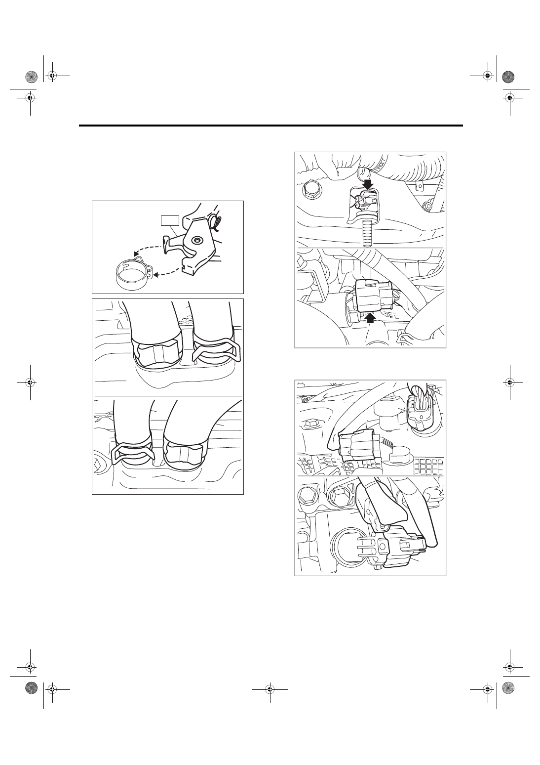
11) Connect the PCV hose (A) and vacuum hose
(B) to the rocker cover.
NOTE:
Use a new clamp for the PCV hose (A), fit the cut
out in the ST with the protrusion on the clamp as
shown in the figure, and lock the clamp.
ST 18353AA000 CLAMP PLIERS
12) Connect the connector to the intake oil flow
control solenoid valve.
13) Connect the connector (A) to the exhaust cam-
shaft position sensor and the connector (B) to the
exhaust oil flow control solenoid valve.
14) Install the ignition coil. <Ref. to IG(STI)-7, IN-
ME-04374
ST
ME-05768
(A)
(B)
(A)
(B)
ME-05990
ME-05025
(B)
(B)
(A)
(A)

ME(STI)-68
Camshaft
MECHANICAL
15) Install the air duct B (B) to the rocker cover LH
and the air duct A (A).
Tightening torque:
6.4 N·m (0.7 kgf-m, 4.7 ft-lb)
16) Fix the engine harness to the rocker cover RH
with clips (A).
17) Install the timing belt cover. <Ref. to ME(STI)-
49, INSTALLATION, Timing Belt Cover.>
18) Install the crank pulley. <Ref. to ME(STI)-47,
19) Install the rear side belt. <Ref. to ME(STI)-41,
REAR SIDE BELT, INSTALLATION, V-belt.>
20) Install the engine to the vehicle. <Ref. to
ME(STI)-34, INSTALLATION, Engine Assembly.>
C: INSPECTION
1) Measure the bend, and repair or replace if nec-
essary.
Camshaft bend limit:
0.020 mm (0.00079 in)
2) Check the journal for damage and wear. Re-
place if faulty.
3) Check the cutout portion used for camshaft sen-
sor for damage. Replace if faulty.
4) Check the cam face condition, and remove the
minor faults by grinding with oil stone. If offset wear
occurs, replace it.
5) Measure the cam lobe height “H” and cam base
circle diameter “A”. If it exceeds the standard or off-
set wear occurs, replace it.
Cam lobe height H:
Standard
Intake
46.55 — 46.65 mm (1.833 — 1.837 in)
Exhaust
46.75 — 46.85 mm (1.841 — 1.844 in)
Cam base circle diameter A:
Standard
37.0 mm (1.457 in)
6) Measure the outside diameter of camshaft jour-
nal. If the journal diameter is not within specifica-
tion, check the oil clearance.
ME-04953
(B)
(A)
ME-04952
(A)
Camshaft journal
Front
Center, rear
Standard
mm (in)
37.946 — 37.963
(1.4939 — 1.4946)
29.946 — 29.963
(1.1790 — 1.1796)
ME-00118
ME-00276
H
A
ME(STI)-69
Camshaft
MECHANICAL
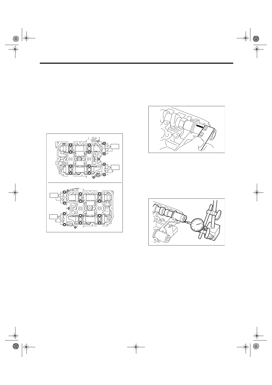
7) Measure the oil clearance of camshaft journal.
(1) Clean the camshaft cap and cylinder head
camshaft journal.
(2) Place the camshaft on cylinder head. (With-
out installing the valve lifter)
(3) Place a plastigauge across each camshaft
journals.
(4) Gradually tighten the camshaft cap in at
least two steps, in alphabetical order shown in
the figure, and then tighten to the specified
torque. Do not turn the camshaft.
Tightening torque:
T1: 9.75 N·m (1.0 kgf-m, 7.2 ft-lb)
T2: 20 N·m (2.0 kgf-m, 14.8 ft-lb)
(5) Remove the camshaft cap.
(6) Measure the widest point of the plastigauge
on each journal. If oil clearance exceeds the
standard, replace the camshaft. If necessary,
replace the camshaft caps and cylinder head as
a set.
Camshaft oil clearance:
Standard
0.037 — 0.072 mm (0.0015 — 0.0028 in)
(7) Completely remove the plastigauge.
8) Measure the thrust clearance with setting the
dial gauge at end surface of camshaft. If the thrust
clearance is not within the standard or there is off-
set wear, replace the camshaft caps and cylinder
head as a set. If necessary replace the camshaft.
Camshaft thrust clearance:
Standard
0.068 — 0.116 mm (0.0027 — 0.0047 in)
ME-05980
(G)
(E)
(C)
(A)
(K)
(L)
(J)
(I)
(B)
(D)
(H)
(F)
(G)
(E)
(C)
(A)
(K)
(L)
(J)
(I)
(B)
(D)
(H)
(F)
T1
T2
T1
T2
T2
T2
T1
T1
ME-00119
ME-00121
Нет комментариевНе стесняйтесь поделиться с нами вашим ценным мнением.
Текст