Subaru Impreza 3 / Impreza WRX / Impreza WRX STI. Service manual — part 543
VDC(diag)-71
Diagnostic Procedure with Diagnostic Trouble Code (DTC)
VEHICLE DYNAMICS CONTROL (VDC) (DIAGNOSTICS)
AB:DTC C0051 VALVE RELAY
DTC DETECTING CONDITION:
Defective valve relay
TROUBLE SYMPTOM:
• ABS does not operate.
• EBD does not operate.
• VDC does not operate.
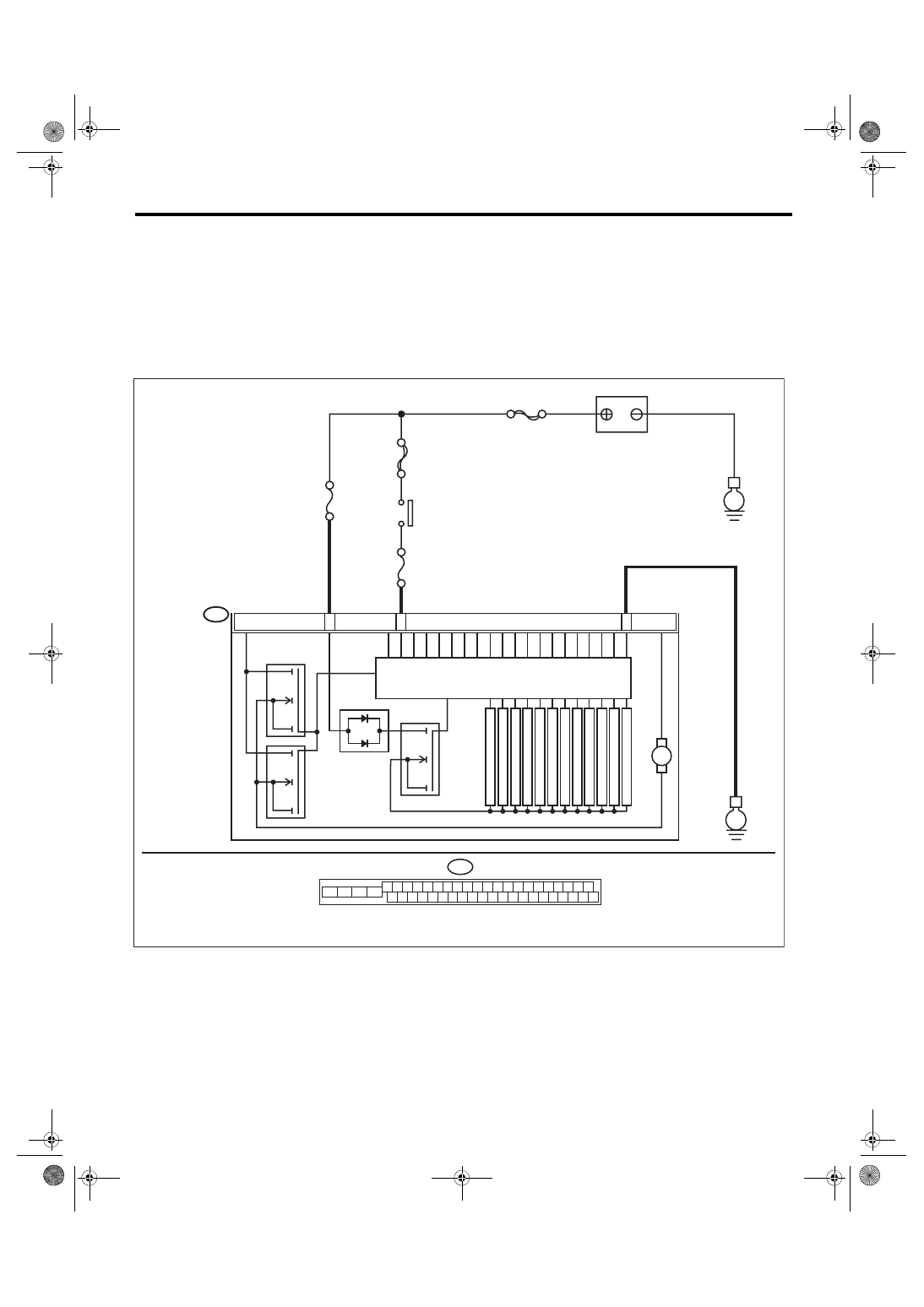
WIRING DIAGRAM:
Vehicle Dynamics Control System <Ref. to WI-67, Vehicle Dynamics Control System.>
B310
E
24
25
VDCCM & H/U
2
8
PUMP MO
T
OR
M
FL INLET
MAIN SBF
SBF-6
No.1
No.33
E
BATTERY
IGNITION
SWITCH
SOLENOID
V
AL
VE
FR INLET
RL INLET
RR INLET
FL OUTLET
FR OUTLET
RL OUTLET
RR OUTLET
P
R
IM
A
RY
C
U
T
S
E
C
O
N
D
A
RY
C
U
T
P
R
IM
A
RY
S
U
C
T
IO
N
MO
T
OR RELA
Y
VALVE RELAY
S
E
C
O
N
D
A
RY
S
U
C
T
IO
N
B310
4 5 6 7 8 9
26 27 28 29 30
2 3
1
31 32 33 34 35 36
10 11
14 15 16 17 18 19
37 38 39 40
12 13
41 42 43 44 45 46
20 21
23 24
22
25
VDC00466
VDC(diag)-72
Diagnostic Procedure with Diagnostic Trouble Code (DTC)
VEHICLE DYNAMICS CONTROL (VDC) (DIAGNOSTICS)
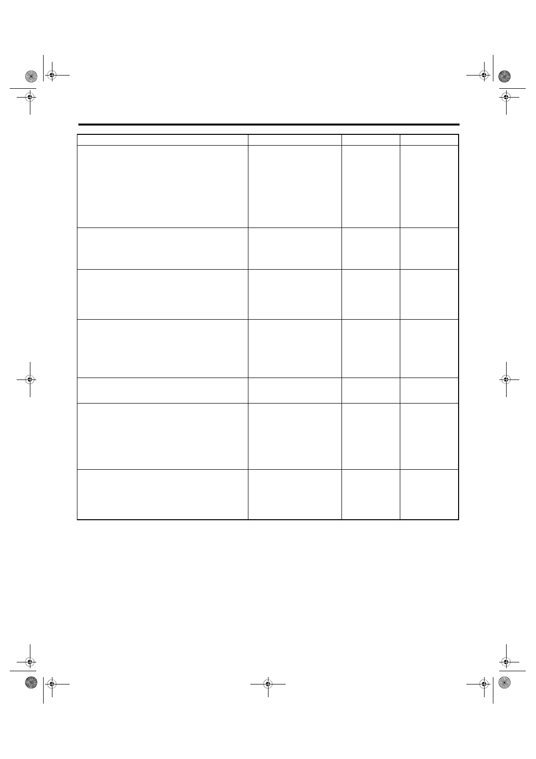
Step
Check
Yes
No
1
CHECK VDCCM&H/U INPUT VOLTAGE.
1) Turn the ignition switch to OFF.
2) Disconnect the connector from the
VDCCM&H/U.
3) Run the engine at idle.
4) Measure the voltage between VDCCM&H/U
connector and chassis ground.
Connector & terminal
(B310) No. 28 (+) — Chassis ground (–):
(B310) No. 24 (+) — Chassis ground (–):
Is the voltage 10 — 15 V?
Repair the power
supply circuit.
2
CHECK VDCCM&H/U INPUT VOLTAGE.
Calculate the voltage difference measured in
step 1.
A: (B310) No. 28 (+) — Chassis ground (–):
B: (B310) No. 24 (+) — Chassis ground (–):
Is the voltage difference
between A and B 2 V or more?
Repair the power
supply circuit.
3
CHECK VDCCM&H/U GROUND CIRCUIT.
1) Turn the ignition switch to OFF.
2) Measure the resistance between
VDCCM&H/U connector and chassis ground.
Connector & terminal
(B310) No. 25 — Chassis ground:
Is the resistance less than 10
Ω?
Repair the
VDCCM&H/U
ground harness.
4
CHECK VDCCM&H/U VALVE RELAY.
Measure the resistance between VDCCM&H/U
terminals.
Terminals
No. 24 — No. 25:
Is the resistance 1 MΩ or
more?
Replace the
VDCCM&H/U.
<Ref. to VDC-8,
VDC Control Mod-
ule and Hydraulic
Control Unit
(VDCCM&H/U).>
5
CHECK POOR CONTACT OF CONNEC-
TORS.
Is there poor contact of connec-
tor between generator, battery
and VDCCM&H/U?
Repair the connec-
tor.
6
CHECK VDCCM&H/U.
1) Connect all connectors.
2) Clear the memory. <Ref. to VDC(diag)-27,
Clear Memory Mode.>
3) Perform the Inspection Mode. <Ref. to
VDC(diag)-26, Inspection Mode.>
4) Read the DTC.
Is the same DTC displayed?
7
CHECK OTHER DTC DETECTION.
Is any other DTC displayed?
Temporary poor
contact occurs.
VDC(diag)-73
Diagnostic Procedure with Diagnostic Trouble Code (DTC)
VEHICLE DYNAMICS CONTROL (VDC) (DIAGNOSTICS)
AC:DTC C0052 MOTOR AND MOTOR RELAY OFF FAILURE
DTC DETECTING CONDITION:
• Defective motor and motor relay
• Defective harness connector
TROUBLE SYMPTOM:
• ABS does not operate.
• VDC does not operate.
• EBD may not operate.
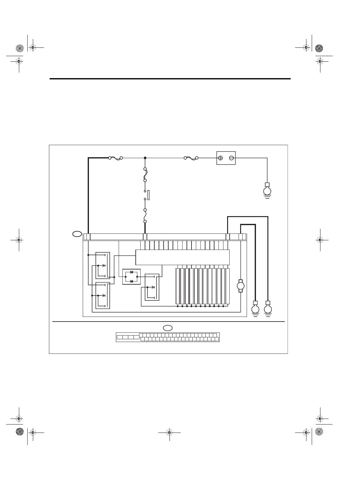
WIRING DIAGRAM:
Vehicle Dynamics Control System <Ref. to WI-67, Vehicle Dynamics Control System.>
B310
E
23
25
VDCCM & H/U
2
8
PUMP MO
T
OR
M
FL INLET
MAIN SBF
SBF-6
No.33
E
BATTERY
IGNITION
SWITCH
SOLENOID
V
AL
VE
MO
T
OR RELA
Y
VALVE RELAY
FR INLET
RL INLET
RR INLET
FL OUTLET
FR OUTLET
RL OUTLET
RR OUTLET
P
R
IM
A
RY
C
U
T
S
E
C
O
N
D
A
RY
C
U
T
P
R
IM
A
RY
S
U
C
T
IO
N
SBF-1
E
22
S
E
C
O
N
D
A
RY
S
U
C
T
IO
N
B310
4 5 6 7 8 9
26 27 28 29 30
2 3
1
31 32 33 34 35 36
10 11
14 15 16 17 18 19
37 38 39 40
12 13
41 42 43 44 45 46
20 21
23 24
22
25
VDC00467
VDC(diag)-74
Diagnostic Procedure with Diagnostic Trouble Code (DTC)
VEHICLE DYNAMICS CONTROL (VDC) (DIAGNOSTICS)
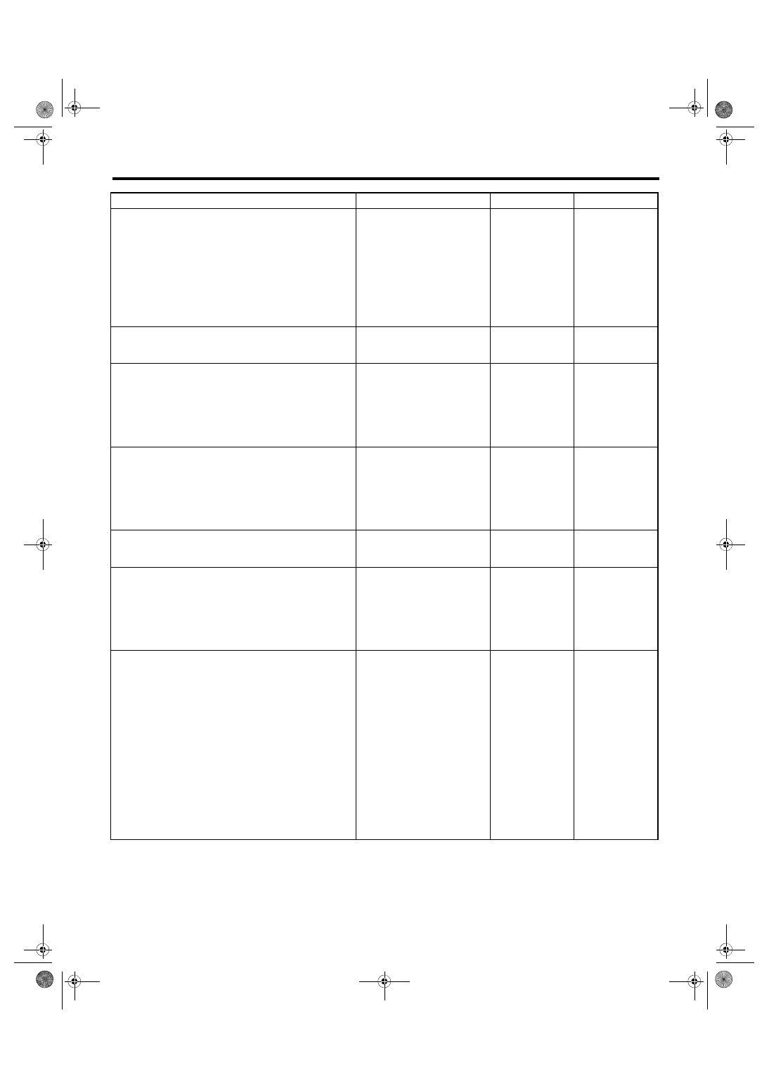
Step
Check
Yes
No
1
CHECK VDCCM&H/U INPUT VOLTAGE.
1) Turn the ignition switch to OFF.
2) Disconnect the connector from the
VDCCM&H/U.
3) Turn the ignition switch to ON.
4) Measure the voltage between VDCCM&H/U
connector and chassis ground.
Connector & terminal
(B310) No. 23 (+) — Chassis ground (–):
(B310) No. 28 (+) — Chassis ground (–):
Is the voltage 10 — 15 V?
Repair the
VDCCM&H/U
power supply cir-
cuit.
2
CHECK INSTALLATION OF MOTOR
GROUND.
Is the motor ground terminal
installation bolt tightened 33
N·m (3.4 kgf-m, 24.3 ft-lb)?
Tighten the motor
ground terminal
installation bolt.
3
CHECK VDCCM&H/U GROUND CIRCUIT.
1) Turn the ignition switch to OFF.
2) Measure the resistance between
VDCCM&H/U connector and chassis ground.
Connector & terminal
(B310) No. 25 — Chassis ground:
(B310) No. 22 — Chassis ground:
Is the resistance less than 10
Ω?
Repair the
VDCCM&H/U
ground harness.
4
CHECK VDCCM&H/U MOTOR RELAY.
Measure the resistance between VDCCM&H/U
terminals.
Terminals
No. 23 — No. 22:
Is the resistance 1 MΩ or
more?
Replace the
VDCCM&H/U.
<Ref. to VDC-8,
VDC Control Mod-
ule and Hydraulic
Control Unit
(VDCCM&H/U).>
5
CHECK POOR CONTACT OF CONNEC-
TORS.
Turn the ignition switch to OFF.
Is there poor contact of connec-
tor between generator, battery
and VDCCM&H/U?
Repair the connec-
tor.
6
CHECK VDCCM&H/U.
1) Connect all connectors.
2) Clear the memory. <Ref. to VDC(diag)-27,
Clear Memory Mode.>
3) Perform the Inspection Mode. <Ref. to
VDC(diag)-26, Inspection Mode.>
4) Read the DTC.
Is the same DTC displayed?
Replace the
VDCCM&H/U.
<Ref. to VDC-8,
VDC Control Mod-
ule and Hydraulic
Control Unit
(VDCCM&H/U).>
7
CHECK OTHER DTC DETECTION.
Is any other DTC displayed?
Temporary poor
contact occurs.
NOTE:
Though the ABS
warning light re-
mains on at this
time, this is normal.
Drive the vehicle at
12 km/h (7 MPH)
or more in order to
turn ABS warning
light off. Be sure to
drive the vehicle
and check that the
warning light goes
off.
Нет комментариевНе стесняйтесь поделиться с нами вашим ценным мнением.
Текст