Subaru Impreza 3 / Impreza WRX / Impreza WRX STI. Service manual — part 47
EC(STI)-2
General Description
EMISSION CONTROL (AUX. EMISSION CONTROL DEVICES)
1. General Description
A: COMPONENT
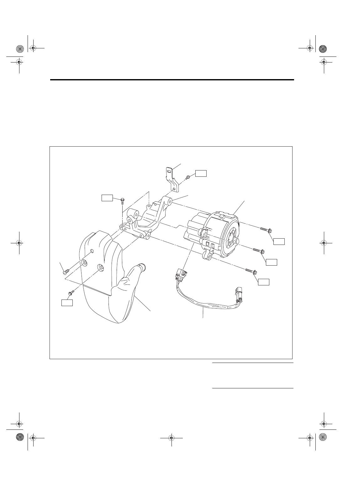
1. CANISTER, PURGE CONTROL SOLENOID VALVE, PRESSURE CONTROL SOLENOID
VALVE ASSEMBLY, SHUT VALVE, LEAK CHECK VALVE, AND DRAIN SEPARATOR
2. SECONDARY AIR PUMP
(1)
Secondary air pump
(4)
Resonator
Tightening torque: N·m (kgf-m, ft-lb)
(2)
Clip
(5)
Harness stay
T1: 6.4 (0.7, 4.7)
(3)
Secondary air pump bracket
(6)
Secondary air pump harness
T2: 9 (0.9, 6.6)
T3: 19 (1.9, 14.0)
EC-02684
(1)
(3)
T2
T2
T2
T3
(4)
(2)
T1
T1
(6)
(5)
EC(STI)-3
General Description
EMISSION CONTROL (AUX. EMISSION CONTROL DEVICES)
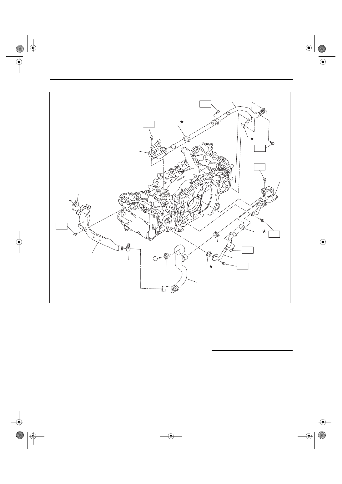
3. SECONDARY AIR COMBINATION VALVE
(A)
To secondary air pump
(B)
To resonator
(1)
Gasket
(7)
Air duct A
Tightening torque: N·m (kgf-m, ft-lb)
(2)
Gasket
(8)
Air duct B
T1: 6.4 (0.7, 4.7)
(3)
Gasket
(9)
Secondary air combination valve
LH
T2: 9 (0.9, 6.6)
(4)
Clip
(10) Secondary air pipe LH
T3: 19 (1.9, 14.0)
(5)
Secondary air pipe RH
(11) Gasket
(6)
Secondary air combination valve
RH
EC-02717
(1)
(2)
T2
T3
T2
T3
T3
T2
T3
T1
(3)
(4)
(4)
(4)
(5)
(6)
(7)
(8)
(9)
(10)
(11)
(4)
(A)
(B)
A
A
EC(STI)-4
General Description
EMISSION CONTROL (AUX. EMISSION CONTROL DEVICES)
B: CAUTION
• Prior to starting work, pay special attention to the following:
1. Always wear work clothes, a work cap, and protective shoes. Additionally, wear a helmet, protective
goggles, etc. if necessary.
2. Protect the vehicle using a seat cover, fender cover, etc.
3. Prepare the service tools, clean cloth, containers to catch grease and oil, etc.
• Vehicle components are extremely hot immediately after driving. Be wary of receiving burns from heated
parts.
• When performing a repair, identify the cause of trouble and avoid unnecessary removal, disassembly and
replacement.
• Before disconnecting connectors of sensors or units, be sure to disconnect the ground cable from battery.
• Always use the jack-up point when the shop jacks or rigid racks are used to support the vehicle.
• Remove contamination including dirt and corrosion before removal, installation, disassembly or assembly.
• Keep the removed parts in order and protect them from dust and dirt.
• All removed parts, if to be reused, should be reinstalled in the original positions with attention to the correct
directions, etc.
• Bolts, nuts and washers should be replaced with new parts as required.
• Be sure to tighten the fasteners including bolts and nuts to the specified torque.
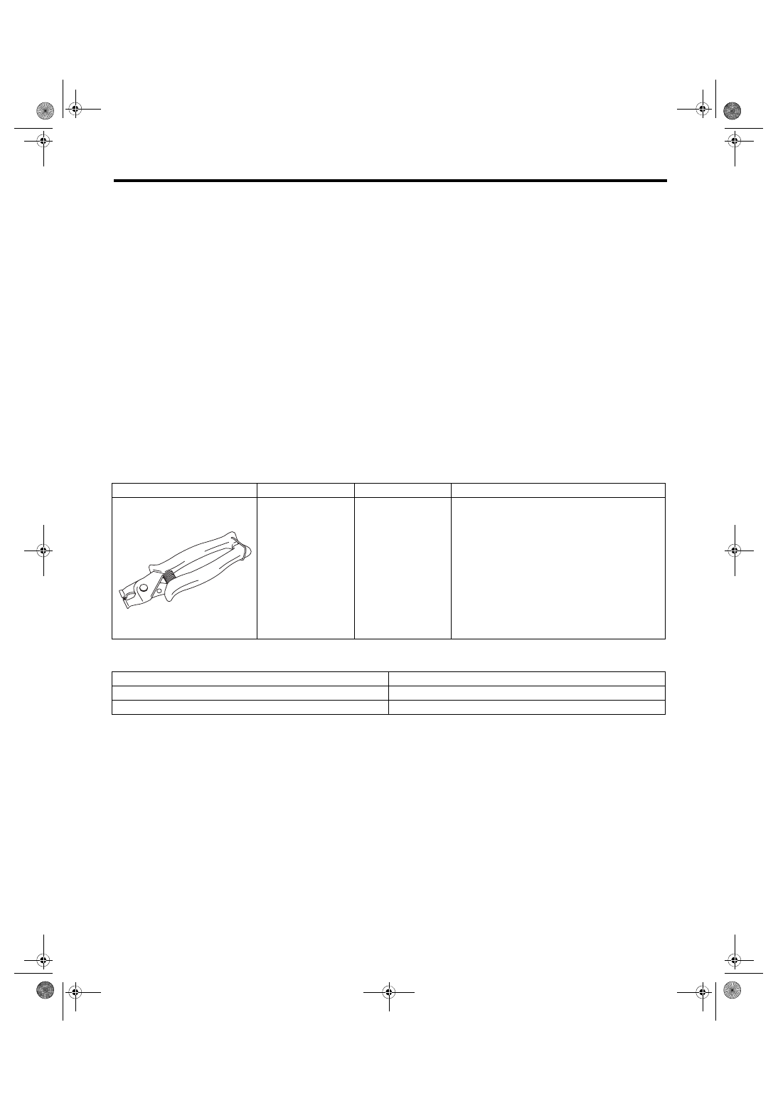
C: PREPARATION TOOL
1. SPECIAL TOOL
2. GENERAL TOOL
ILLUSTRATION
TOOL NUMBER
DESCRIPTION
REMARKS
18353AA000
CLAMP PLIERS
• Used for removing and installing the PCV
hose.
• This tool is made by the French company
CAILLAU. (code) 54.0.000.205
To make it easier to obtain, it has been provided
with a tool number.
TOOL NAME
REMARKS
Circuit tester
Used for measuring resistance.
Mighty Vac
Used for inspecting the fuel tank pressure sensor.
ST18353AA000
EC(STI)-5
Front Catalytic Converter
EMISSION CONTROL (AUX. EMISSION CONTROL DEVICES)
2. Front Catalytic Converter
A: REMOVAL
The front catalytic converter is integrated into the
center exhaust pipe (front). Refer to “Center Ex-
haust Pipe” for removal procedures. <Ref. to
EX(STI)-8, REMOVAL, Center Exhaust Pipe.>
B: INSTALLATION
The front catalytic converter is integrated into the
center exhaust pipe (front). Refer to “Center Ex-
haust Pipe” for installation procedures. <Ref. to
EX(STI)-9, INSTALLATION, Center Exhaust
C: INSPECTION
1) Check the connections and welds for exhaust
leaks.
2) Make sure there are no holes or rusting.
Нет комментариевНе стесняйтесь поделиться с нами вашим ценным мнением.
Текст