Subaru Impreza 3 / Impreza WRX / Impreza WRX STI. Service manual — part 311
EN(H4DOTC)(diag)-468
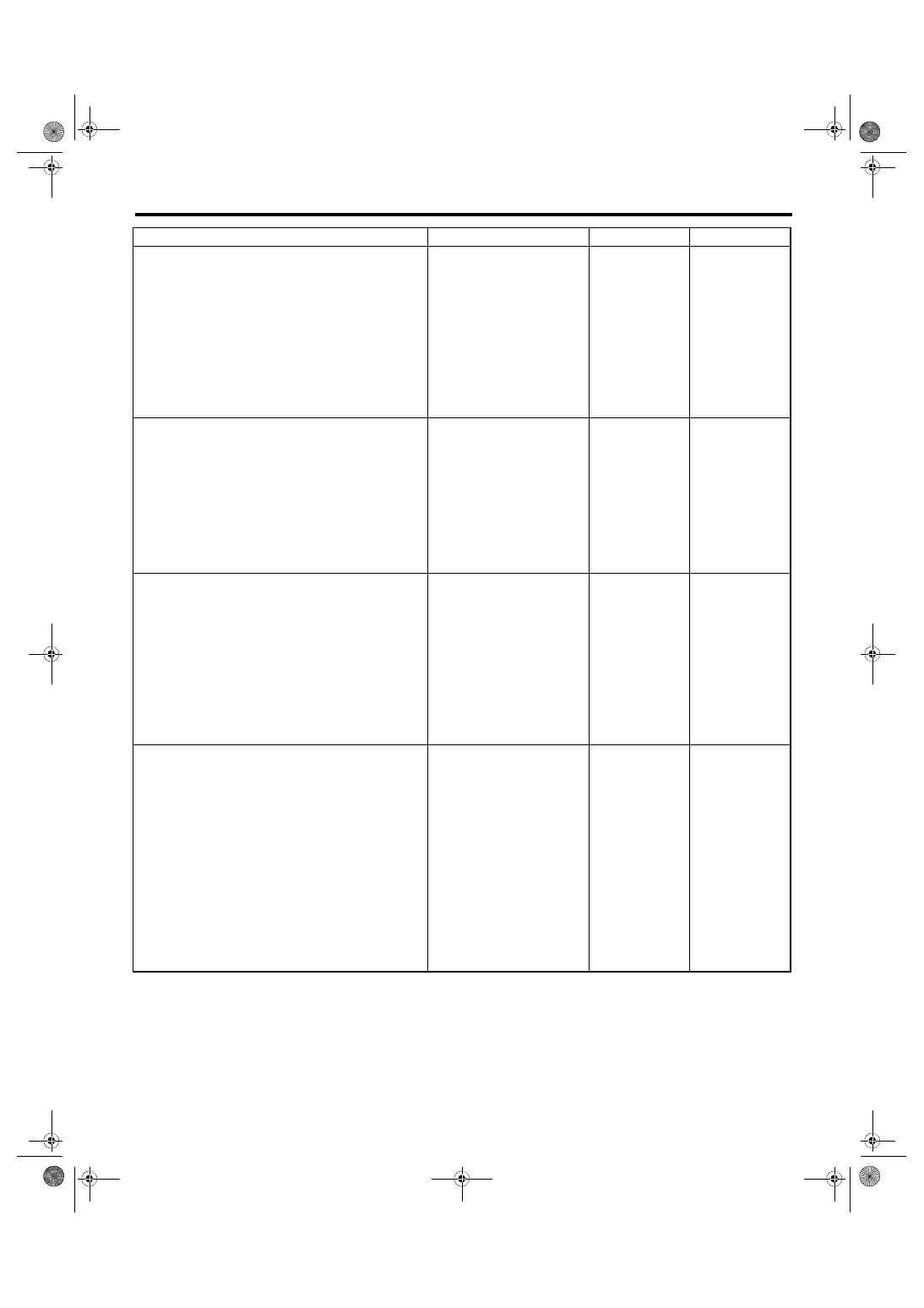
Diagnostic Procedure without Diagnostic Trouble Code (DTC)
ENGINE (DIAGNOSTICS)
2
CHECK HARNESS BETWEEN COMBINA-
TION METER AND MULTI-SELECT SWITCH
CONNECTOR.
1) Disconnect the connector from multi-select
switch.
2) Measure the resistance of harness between
combination meter and multi-select switch con-
nector.
Connector & terminal
(i10) No. 33 — (R33) No. 8:
(i10) No. 35 — (R33) No. 5:
Is the resistance less than 1 Ω? Go to step
Repair the harness
and connector.
NOTE:
In this case, repair
the following item:
• Open circuit in
harness between
combination meter
and
multi-select
switch connector
• Poor contact of
coupling connector
3
CHECK HARNESS BETWEEN COMBINA-
TION METER AND MULTI-SELECT SWITCH
CONNECTOR.
Measure the resistance between multi-select
switch connector and chassis ground.
Connector & terminal
(R33) No. 8 — Chassis ground:
(R33) No. 5 — Chassis ground:
Is the resistance 1 MΩ or
more?
Repair the ground
short circuit in har-
ness between
combination meter
and multi-select
switch connector.
4
CHECK HARNESS BETWEEN COMBINA-
TION METER AND CHASSIS GROUND.
Measure the resistance of harness between
combination meter and chassis ground.
Connector & terminal
(i10) No. 21 — Chassis ground:
(i10) No. 22 — Chassis ground:
Is the resistance less than 5 Ω? Go to step
Repair the harness
and connector.
NOTE:
In this case, repair
the following item:
• Open circuit in
harness between
combination meter
and
chassis
ground
• Poor contact of
coupling connector
5
RECHECK FAULT.
1) Connect all connectors.
2) Switch SI-DRIVE modes.
Is there any fault?
The circuit has
returned to a nor-
mal condition at
this time. Repro-
duce the failure,
and then perform
the diagnosis
again.
NOTE:
In this case, tem-
porary poor con-
tact of connector,
temporary open or
short circuit of har-
ness may be the
cause.
Step
Check
Yes
No
EN(H4DOTC)(diag)-469
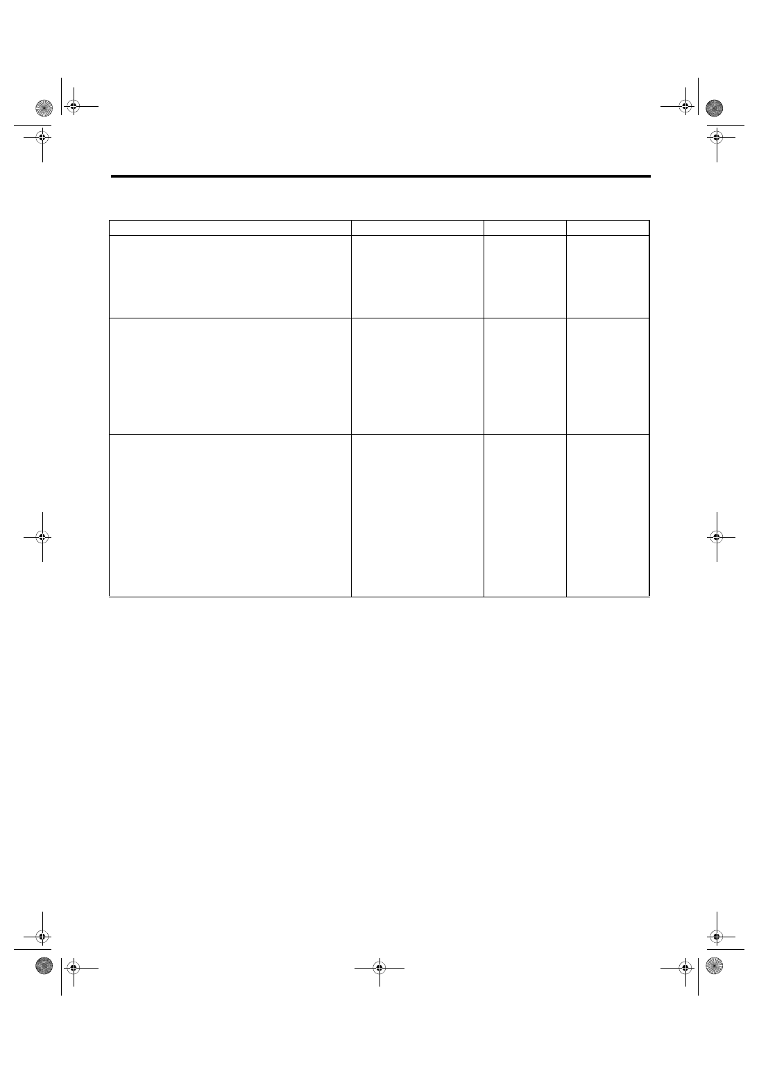
Diagnostic Procedure without Diagnostic Trouble Code (DTC)
ENGINE (DIAGNOSTICS)
2. “S” BLINKS ON SI-DRIVE MODE DISPLAY IN THE COMBINATION METER APPROX. 5
SECONDS AFTER SWITCHING SI-DRIVE MODES
Step
Check
Yes
No
1
CHECK DTC.
Is DTC displayed?
Check the appro-
priate DTC using
the “List of Diag-
nostic Trouble
Code (DTC)” con-
cerning the
respective units.
2
CHECK COMBINATION METER AND
CLOCK DISPLAY.
Check for abnormal indication other than “S”
blinking.
Examples:
• Malfunction indicator light illuminates.
• “Err” is displayed on fuel efficiency display
part.
• Engine coolant temperature gauge does not
move.
Is there any abnormal indica-
tion other than “S” blinking?
3
CHECK COMBINATION METER, ECM AND
BODY INTEGRATED UNIT.
Are the part numbers of combi-
nation meter, ECM and body
integrated unit correct?
Replace the com-
bination meter.
<Ref. to IDI-16,
Combination
Meter.>
EN(H4DOTC)(diag)-470
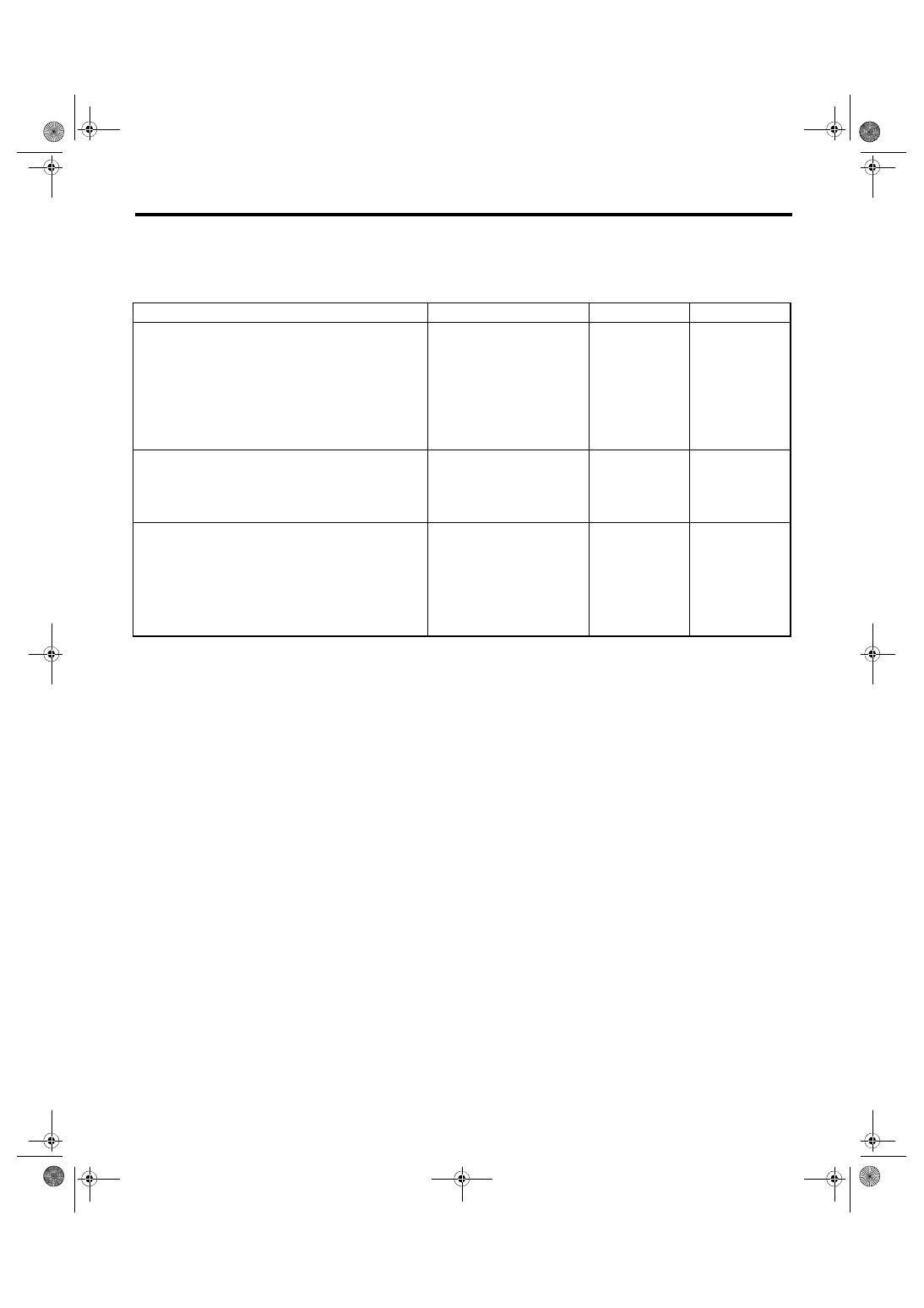
Diagnostic Procedure without Diagnostic Trouble Code (DTC)
ENGINE (DIAGNOSTICS)
3. “S#”, “I” OR “S” BLINKS ON SI-DRIVE MODE DISPLAY IN THE COMBINATION METER
AFTER SWITCHING SI-DRIVE MODES
NOTE:
In this case, there is a fault other than in SI-DRIVE system.
Step
Check
Yes
No
1
CHECK MALFUNCTION INDICATOR LIGHT.
1) Start the engine.
2) Check if malfunction indicator light illumi-
nates.
Does the malfunction indicator
light illuminate?
2
CHECK ENGINE COOLANT TEMPERATURE
GAUGE.
1) Turn the ignition switch to ON.
2) Check the engine coolant temperature
gauge.
Does it indicate overheating?
Inspect for the
cause of overheat-
ing and repair.
3
CHECK COMBINATION METER INDICA-
TION.
1) Turn the ignition switch to ON.
2) Switch SI-DRIVE modes.
3) Check the SI-DRIVE mode display in the
combination meter.
Does “S#”, “I” or “S” of the SI-
DRIVE mode blink in combina-
tion meter?
Replace the com-
bination meter.
<Ref. to IDI-16,
Combination
Meter.>
Perform test driv-
ing to check the
malfunction indica-
tor light and engine
coolant tempera-
ture gauge. Com-
plete the diagnosis
if they are normal.
EN(H4DOTC)(diag)-471
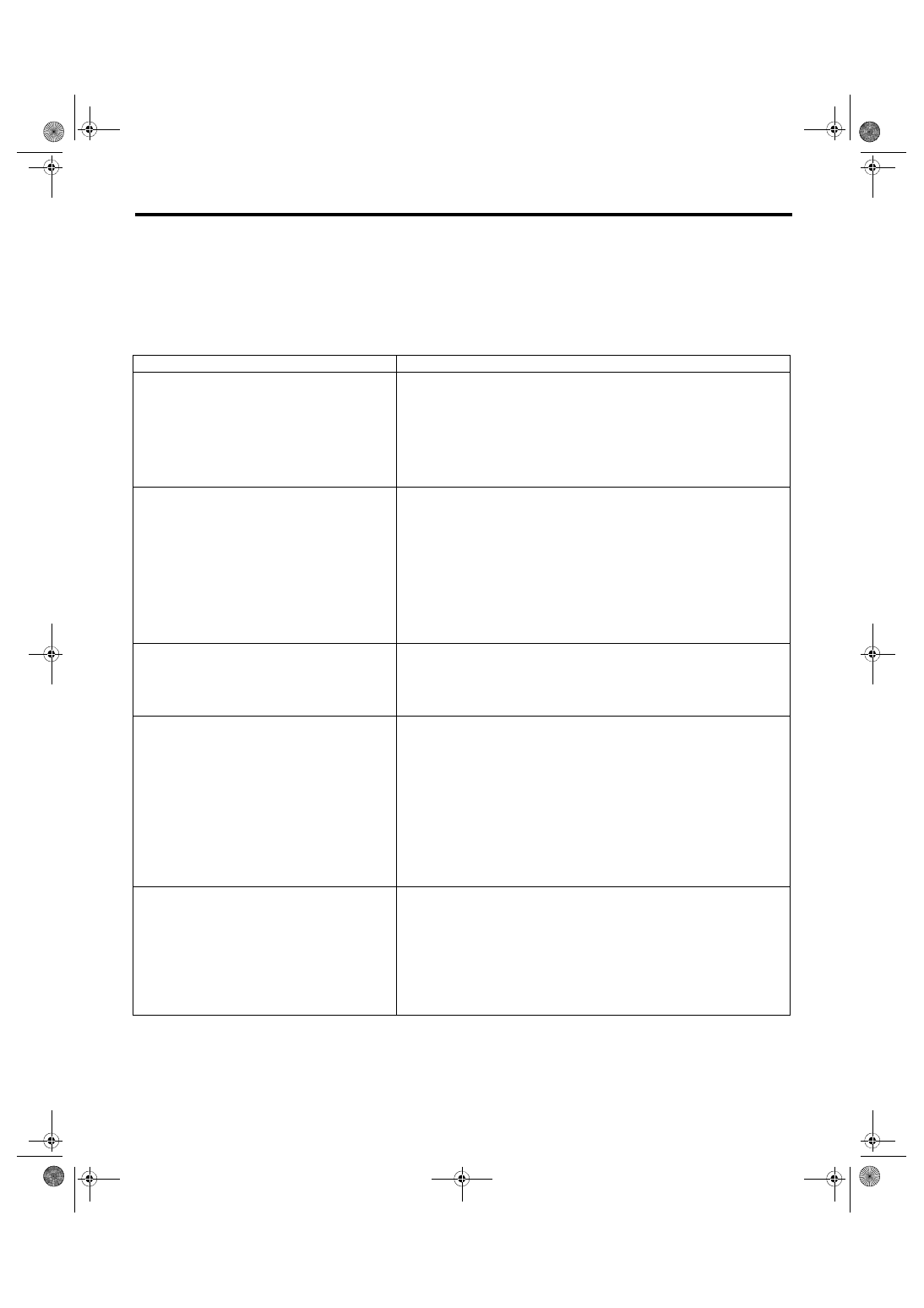
General Diagnostic Table
ENGINE (DIAGNOSTICS)
22.General Diagnostic Table
A: INSPECTION
1. ENGINE
NOTE:
eral.> <Ref. to ME(w/o STI)-103, Engine Trouble in General.>
Symptoms
Faulty parts
1. Engine stalls during idling.
1) Electronic throttle control
2) Manifold absolute pressure sensor
3) Mass air flow and intake air temperature sensor
4) Ignition parts (*1)
5) Engine coolant temperature sensor (*2)
6) Crankshaft position sensor (*3)
7) Camshaft position sensor (*3)
8) Fuel injection parts (*4)
2. Rough idling
1) Electronic throttle control
2) Manifold absolute pressure sensor
3) Mass air flow and intake air temperature sensor
4) Engine coolant temperature sensor (*2)
5) Ignition parts (*1)
6) Air intake system (*5)
7) Fuel injection parts (*4)
8) Crankshaft position sensor (*3)
9) Camshaft position sensor (*3)
10) Oxygen sensor
11) Fuel pump and fuel pump relay
3. Engine does not return to idle.
1) Electronic throttle control
2) Engine coolant temperature sensor
3) Manifold absolute pressure sensor
4) Mass air flow and intake air temperature sensor
5) Accelerator pedal position sensor
4. Poor acceleration
1) Manifold absolute pressure sensor
2) Mass air flow and intake air temperature sensor
3) Electronic throttle control
4) Fuel injection parts (*4)
5) Fuel pump and fuel pump relay
6) Engine coolant temperature sensor (*2)
7) Crankshaft position sensor (*3)
8) Camshaft position sensor (*3)
9) A/C switch and A/C relay
10) Engine torque control signal circuit
11) Ignition parts (*1)
12) Accelerator pedal position sensor
5. Engine stalls, hesitates, or sputters at accelera-
tion.
1) Manifold absolute pressure sensor
2) Mass air flow and intake air temperature sensor
3) Engine coolant temperature sensor (*2)
4) Crankshaft position sensor (*3)
5) Camshaft position sensor (*3)
6) Purge control solenoid valve
7) Fuel injection parts (*4)
8) Fuel pump and fuel pump relay
9) Electronic throttle control
Нет комментариевНе стесняйтесь поделиться с нами вашим ценным мнением.
Текст