Subaru Impreza 3 / Impreza WRX / Impreza WRX STI. Service manual — part 449
6MT(diag)-7
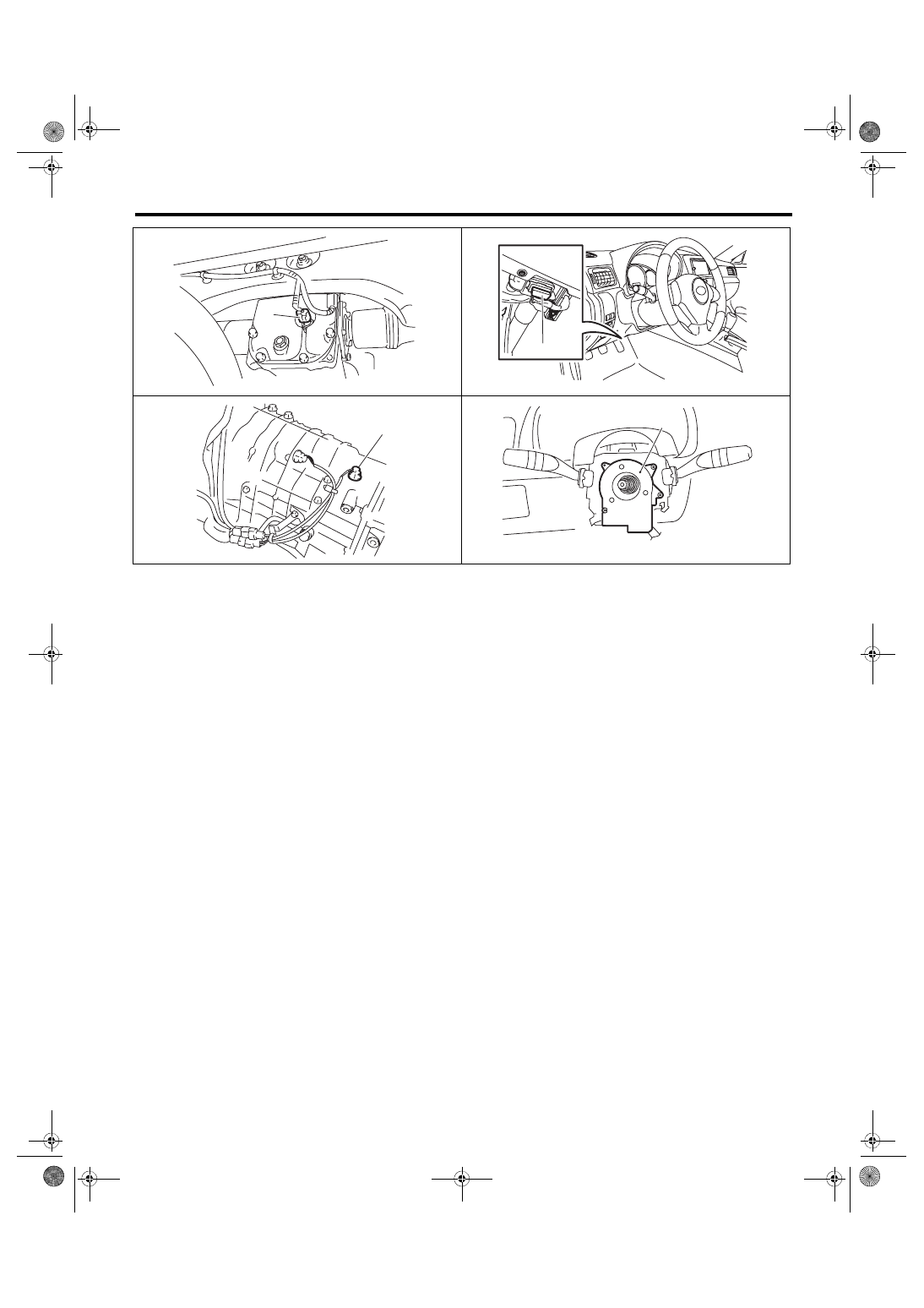
Electrical Component Location
MANUAL TRANSMISSION AND DIFFERENTIAL (DIAGNOSTICS)
MT-02310
(13)
MT-02339
(
14
)
MT-02130
(15)
(16)
MT-02117
6MT(diag)-8
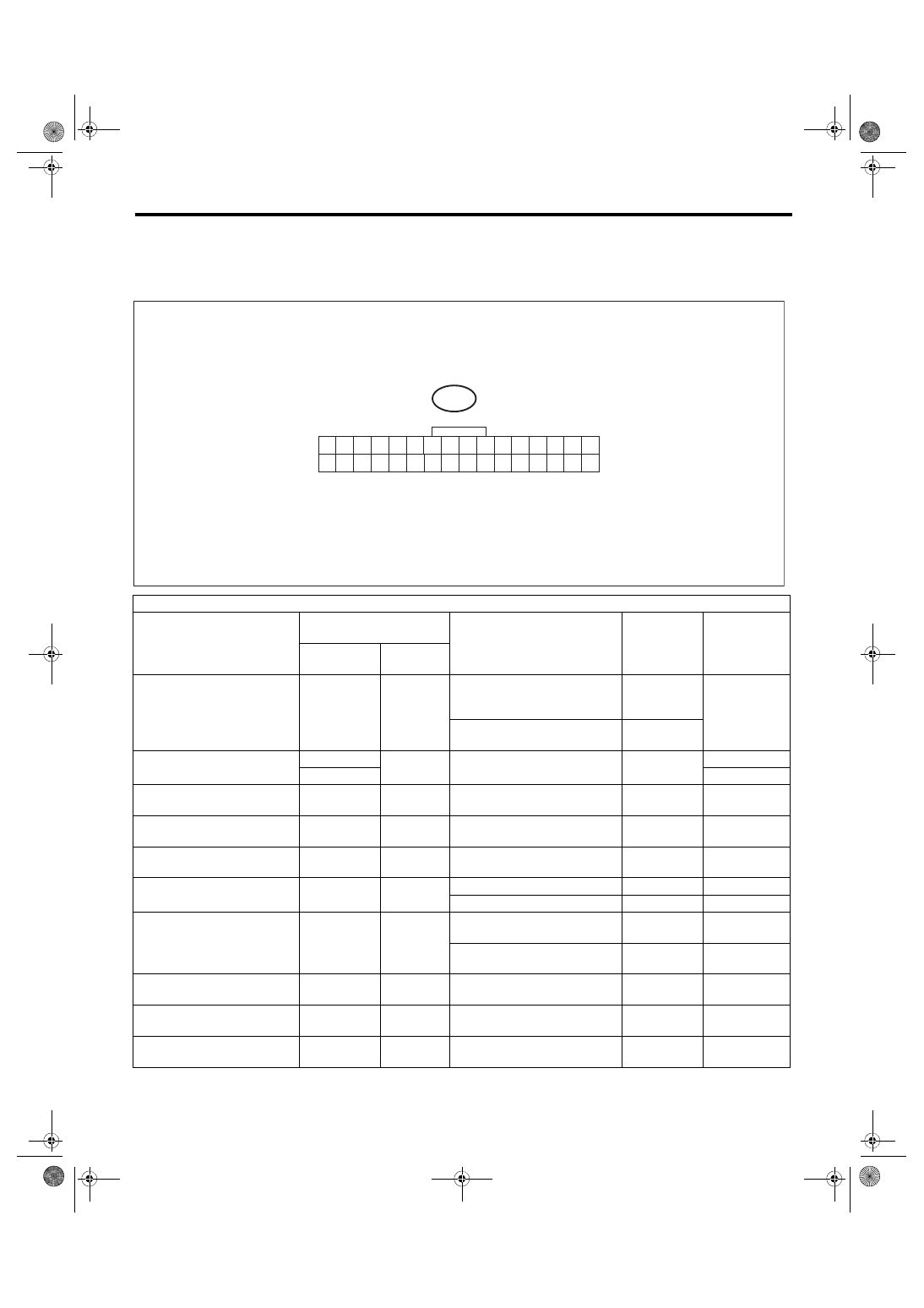
Driver’s Control Center Differential (DCCD) Control Module I/O Signal
MANUAL TRANSMISSION AND DIFFERENTIAL (DIAGNOSTICS)
5. Driver’s Control Center Differential (DCCD) Control Module I/O
Signal
A: ELECTRICAL SPECIFICATION
Check with ignition switch ON.
Item
Measured terminal
(Connector & Terminal No.)
Measuring condition
Voltage (V)
Resistance (Ω)
Positive
terminal
Ground
terminal
DCCD output
(B380) No. 15
(B380)
No. 32
When differential is locked
(when DCCD manual mode dis-
play is locked)
5.5 — 8.0
1.2 — 2.5
When differential is free (When
the parking brake is pulled)
Less than 0.5
DCCD power supply
(B380) No. 13
Chassis
ground
Ignition switch ON
10 — 13
—
(B380) No. 14
—
Backup power supply
(B380) No. 12
Chassis
ground
—
10 — 13
—
Ignition power supply
(B380) No. 11
Chassis
ground
Ignition switch ON
10 — 13
—
DCCD relay
(B380) No. 7
Chassis
ground
Ignition switch ON
Less than 1.0
—
Mode change switch
(B380) No. 6
Chassis
ground
When the switch is not pressed
8.0 or more
—
When the switch is pressed
Less than 1
—
Rear differential oil tempera-
ture switch
(B380) No. 5
Chassis
ground
When the rear differential switch
is ON
0.4 or more
—
When the rear differential switch
is OFF
Less than 8.0
—
CAN communication signal (+)
(B380) No. 2
Chassis
ground
Ignition switch ON
Pulse signal
CAN communication signal (–) (B380) No. 18
Chassis
ground
Ignition switch ON
Pulse signal
Data link signal
(Subaru Select Monitor)
(B380) No. 1
Chassis
ground
—
—
—
MT-01684
B380
8
9
10
24 23
25
11
12
13
14
15
26
27
28
16
17
18
19
20
21
30
31
32
6
7
22
1
2
3
4
5
29
TO
6MT(diag)-9
Driver’s Control Center Differential (DCCD) Control Module I/O Signal
MANUAL TRANSMISSION AND DIFFERENTIAL (DIAGNOSTICS)
B: WIRING DIAGRAM
Refer to “WIRING SYSTEM”. <Ref. to WI-72, Driver’s Control Center Differential Control System.>
System ground circuit
(B380) No. 28
Chassis
ground
—
0
Less than 1.0
(B380) No. 29
Chassis
ground
(B380) No. 30
Chassis
ground
(B380) No. 31
Chassis
ground
System ground circuit
(B380) No. 17
Chassis
ground
—
0
Less than 1.0
Up switch
(B380) No. 22
Chassis
ground
When the switch is not pressed/
is pressed
8.0/1.0
Down switch
(B380) No. 4
Chassis
ground
When the switch is not pressed/
is pressed
8.0/1.0
Check with ignition switch ON.
Item
Measured terminal
(Connector & Terminal No.)
Measuring condition
Voltage (V)
Resistance (Ω)
Positive
terminal
Ground
terminal
6MT(diag)-10
Subaru Select Monitor
MANUAL TRANSMISSION AND DIFFERENTIAL (DIAGNOSTICS)
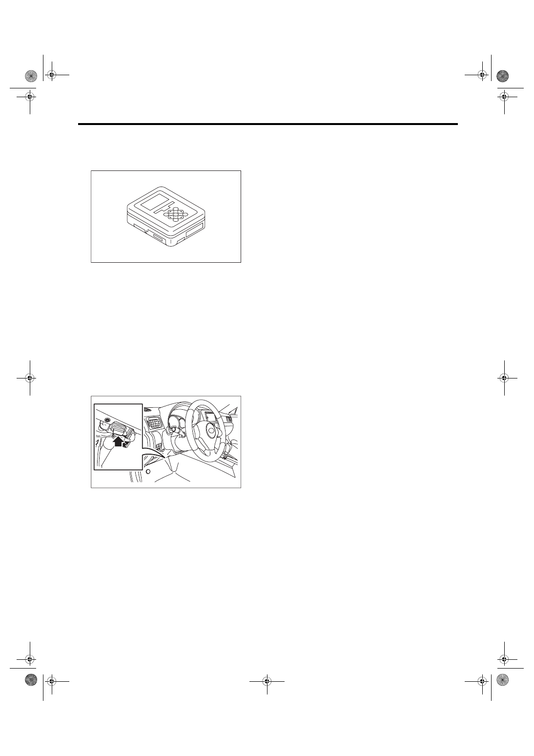
6. Subaru Select Monitor
A: OPERATION
1) Prepare the Subaru Select Monitor kit.
2) Prepare PC with Subaru Select Monitor in-
stalled.
3) Connect the USB cable to SDI (Subaru Diagno-
sis Interface) and USB port on the personal com-
puter (dedicated port for the Subaru Select
Monitor).
NOTE:
The dedicated port for the Subaru Select Monitor
means the USB port which was used to install the
Subaru Select Monitor.
4) Connect the diagnosis cable to SDI.
5) Connect SDI to data link connector located in the
lower portion of the instrument panel (on the driv-
er’s side).
CAUTION:
Do not connect scan tools other than the Suba-
ru Select Monitor.
6) Start the PC.
7) Turn the ignition switch to ON.
8) Run the “PC application for Subaru Select Mon-
itor”.
EN-05692
EN-06148
Нет комментариевНе стесняйтесь поделиться с нами вашим ценным мнением.
Текст