Subaru Impreza 3 / Impreza WRX / Impreza WRX STI. Service manual — part 108
SP(STI)-2
General Description
SPEED CONTROL SYSTEMS
1. General Description
A: SPECIFICATION
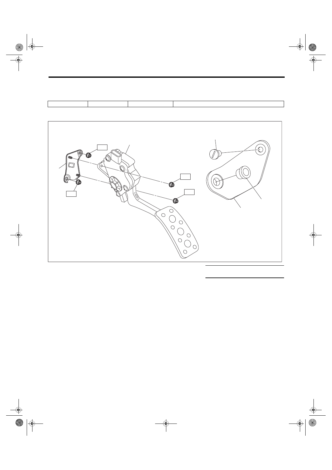
B: COMPONENT
Accelerator pedal
Stroke
At pedal pad
50 — 59 mm (1.97 — 2.32 in)
(1)
Accelerator pedal ASSY
(4)
Accelerator stopper
Tightening torque: N·m (kgf-m, ft-lb)
(2)
Clip
(5)
Accelerator pedal bracket
T: 18 (1.8, 13.3)
(3)
Accelerator plate
SP-02066
T
T
(1)
(5)
(4)
T
T
(3)
(2)
SP(STI)-3
General Description
SPEED CONTROL SYSTEMS
C: CAUTION
• Prior to starting work, pay special attention to the following:
1. Always wear work clothes, a work cap, and protective shoes. Additionally, wear a helmet, protective
goggles, etc. if necessary.
2. Protect the vehicle using a seat cover, fender cover, etc.
3. Prepare the service tools, clean cloth, containers to catch grease and oil, etc.
• Vehicle components are extremely hot immediately after driving. Be wary of receiving burns from heated
parts.
• When performing a repair, identify the cause of trouble and avoid unnecessary removal, disassembly and
replacement.
• Before disconnecting connectors of sensors or units, be sure to disconnect the ground cable from battery.
• Always use the jack-up point when the shop jacks or rigid racks are used to support the vehicle.
• Remove contamination including dirt and corrosion before removal, installation, disassembly or assembly.
• Keep the removed parts in order and protect them from dust and dirt.
• All removed parts, if to be reused, should be reinstalled in the original positions with attention to the correct
directions, etc.
• Bolts, nuts and washers should be replaced with new parts as required.
• Be sure to tighten the fasteners including bolts and nuts to the specified torque.
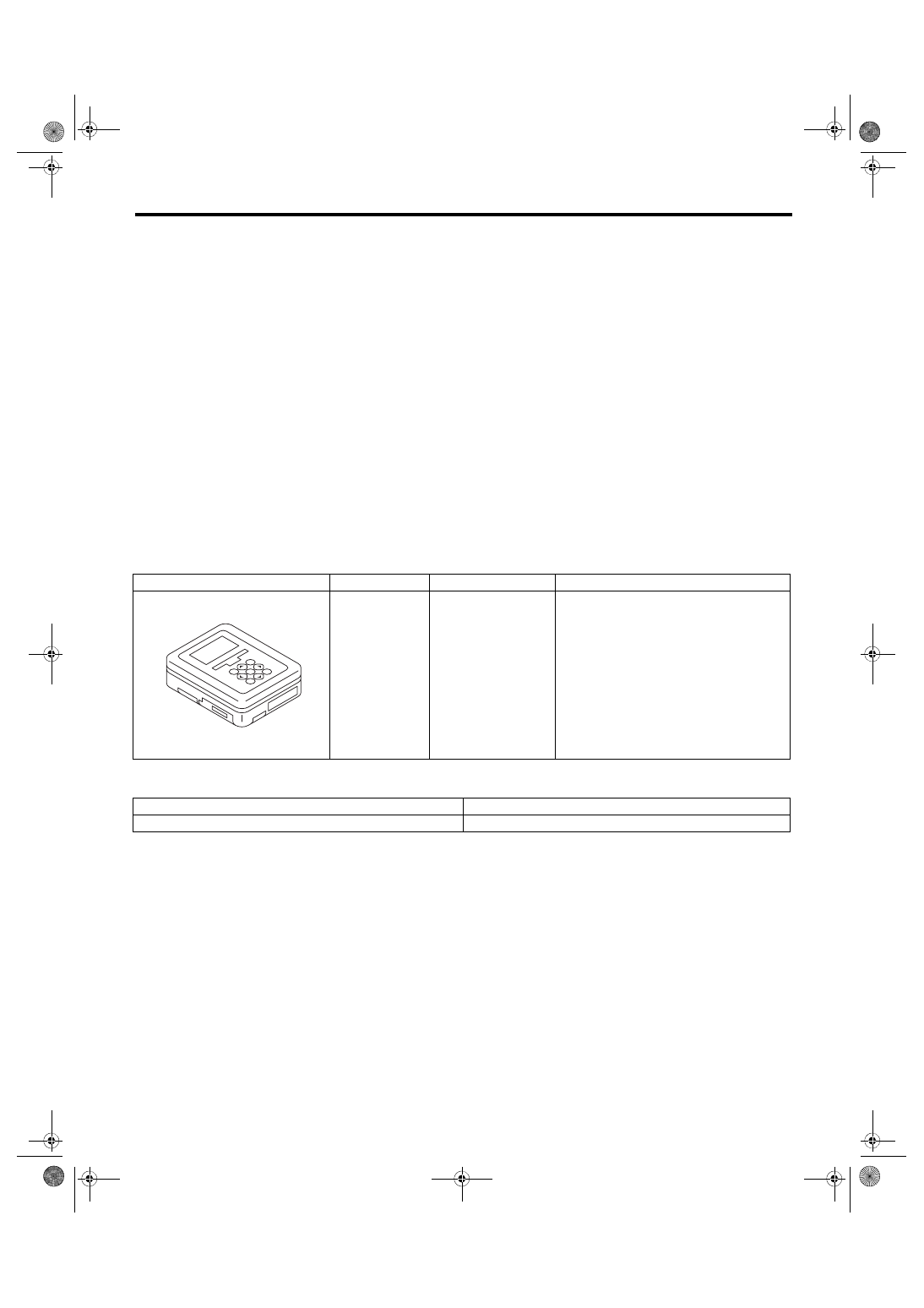
D: PREPARATION TOOL
1. SPECIAL TOOL
2. GENERAL TOOL
ILLUSTRATION
TOOL NUMBER
DESCRIPTION
REMARKS
1B022XU0
SUBARU SELECT
MONITOR III KIT
Used for inspecting the accelerator pedal.
TOOL NAME
REMARKS
Circuit tester
Used for measuring voltage.
ST1B022XU0
SP(STI)-4
Accelerator Pedal
SPEED CONTROL SYSTEMS
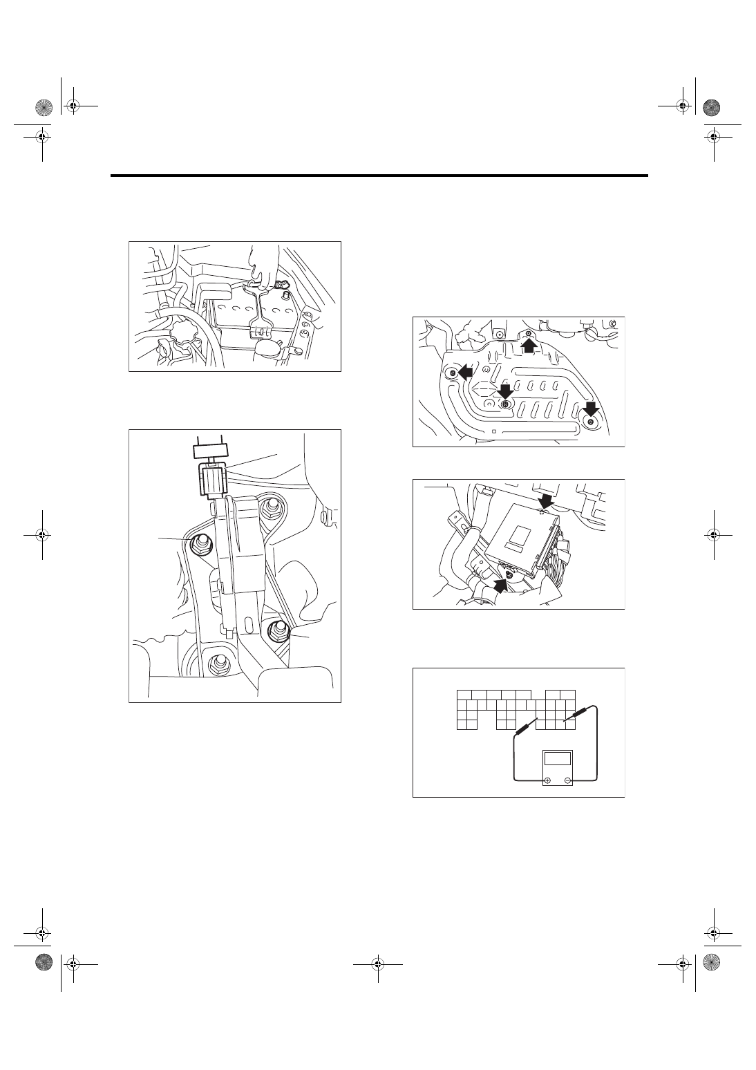
2. Accelerator Pedal
A: REMOVAL
1) Disconnect the ground cable from battery.
2) Disconnect the connector (A).
3) Remove the nut (B) securing accelerator pedal
assembly, and remove the accelerator pedal as-
sembly.
B: INSTALLATION
Install in the reverse order of removal.
Tightening torque:
18 N·m (1.8 kgf-m, 13.3 ft-lb)
C: DISASSEMBLY
NOTE:
The accelerator pedal cannot be disassembled.
D: INSPECTION
1. CHECK ACCELERATOR PEDAL SEN-
SOR AREA (METHOD WITH CIRCUIT
TESTER)
1) Remove the lower inner trim of passenger’s
side. <Ref. to EI-57, REMOVAL, Lower Inner
2) Turn over the floor mat of passenger’s seat.
3) Remove the protect cover.
4) Remove the nuts and bolts which hold the ECM
to the bracket.
5) Turn the ignition switch to ON. (engine OFF)
6) Measure the voltage between ECM connector
terminals.
• Main sensor side
IN-00203
SP-02067
(B)
(B)
(A)
(A) To ECM connector
FU-03416
FU-03417
SP-02078
V
(A)
5
6
7
8
2
1
9
4
3
10
24
22
25
11
12
13
14
15
26
27
28
16
17
18
19
20
21
29
30
23
31
32
33
34
35
SP(STI)-5
Accelerator Pedal
SPEED CONTROL SYSTEMS
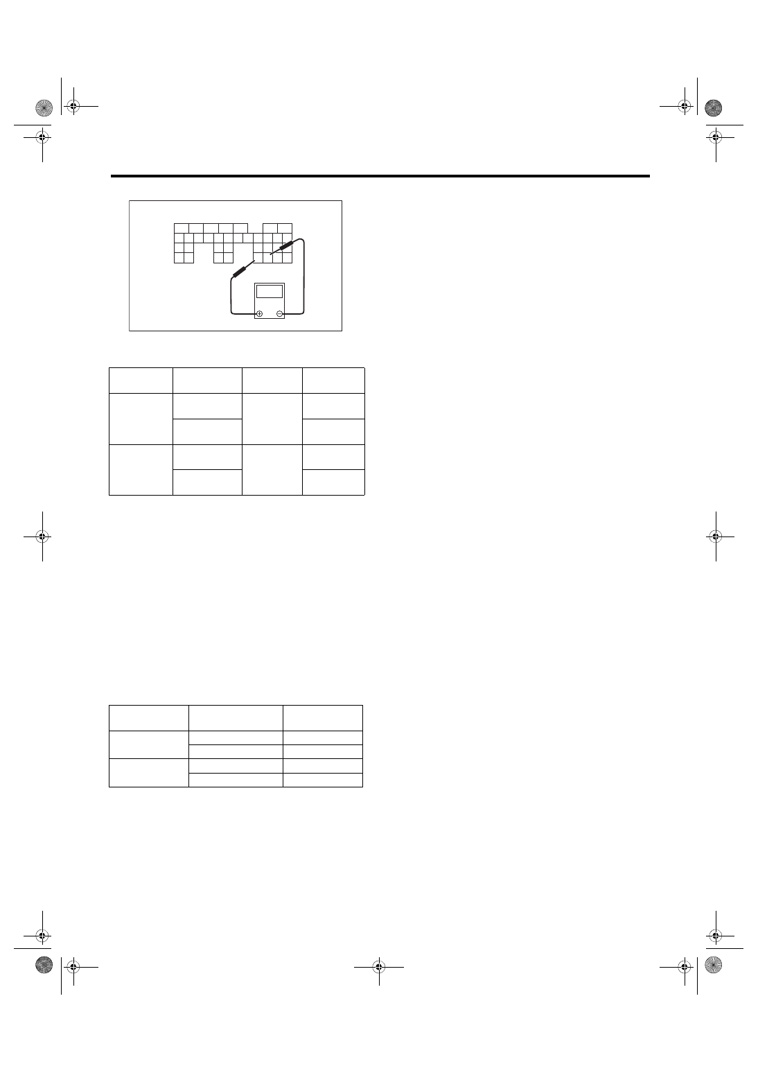
• Sub sensor side
7) After inspection, install the related parts in the
reverse order of removal.
Tightening torque:
7.5 N·m (0.8 kgf-m, 5.5 ft-lb)
2. CHECK ACCELERATOR PEDAL SEN-
SOR AREA (METHOD WITH SUBARU SE-
LECT MONITOR)
1) Turn the ignition switch to ON. (engine OFF)
2) Read the accelerator pedal opening angle signal
and voltage of accelerator pedal sensor using Sub-
aru Select Monitor. <Ref. to EN(H4DOTC)(diag)-
41, READ CURRENT DATA FOR ENGINE (NOR-
MAL MODE), OPERATION, Subaru Select Moni-
3. OTHER INSPECTIONS
1) Check that the accelerator pedal does not have
deformation, cracks or damage.
2) Check for smooth operation when the accelera-
tor pedal is depressed.
3) Check if the accelerator pedal returns to its orig-
inal position smoothly when the pedal is released.
(A) To ECM connector
Accelerator
pedal sensor
Accelerator
pedal
Terminal No.
Standard
Main
Not depressed
(Full closed)
23 (+) and
29 (–)
0.4 — 1.0 V
Depressed
(Full opened)
2.4 — 3.7 V
Sub
Not depressed
(Full closed)
31 (+) and
30 (–)
0.3 — 1.1 V
Depressed
(Full opened)
2.3 — 3.8 V
Accelerator
pedal sensor
Accelerator pedal
opening angle signal
Standard
Main
0.0%
0.4 — 1.0 V
100.0%
2.4 — 3.7 V
Sub
0.0%
0.3 — 1.1 V
100.0%
2.3 — 3.8 V
SP-02079
V
(A)
5
6
7
8
2
1
9
4
3
10
24
22
25
11
12
13
14
15
26
27
28
16
17
18
19
20
21
29
30
23
31
32
33
34
35
Нет комментариевНе стесняйтесь поделиться с нами вашим ценным мнением.
Текст