Subaru Impreza 3 / Impreza WRX / Impreza WRX STI. Service manual — part 785
LAN(diag)-49
Diagnostic Procedure with Diagnostic Trouble Code (DTC)
LAN SYSTEM (DIAGNOSTICS)
3
CHECK DTC.
1) Turn the ignition switch to OFF.
2) Disconnect all control module connectors
(B280, B310, B136, B230, B231, B380) that are
connected to high speed CAN communication
line.
3) Connect the disconnected connectors.
4) Turn the ignition switch to ON.
5) Read the DTC of body integrated unit using
Subaru Select Monitor.
Is U1202 a current malfunc-
tion?
4
CHECK HARNESS.
1) Turn the ignition switch to OFF.
2) Disconnect all control module connectors
(B280, B310, B136, B230, B231, B380) that are
connected to high speed CAN communication
line.
3) Using the tester, check for open, short
(power supply-output short, GND-output short)
in the harness.
Connector & terminal
(B40) No. 6 — (B136) No. 17:
(B40) No. 6 — (B310) No. 35:
(B40) No. 6 — (B230) No. 2:
(B40) No. 6 — (B231) No. 2:
(B40) No. 6 — (B380) No. 2 (with SI-
DRIVE):
(B40) No. 6 — (B280) No. 3:
Is harness normal?
Repair or replace
the harness.
5
CHECK HARNESS.
Using the tester, check for open, short (power
supply-output short, GND-output short) in the
harness.
Connector & terminal
(B40) No. 14 — (B136) No. 28:
(B40) No. 14 — (B310) No. 10:
(B40) No. 14 — (B230) No. 3:
(B40) No. 14 — (B231) No. 1:
(B40) No. 14 — (B380) No. 18 (with SI-
DRIVE):
(B40) No. 14 — (B280) No. 9:
Is harness normal?
Repair or replace
the harness.
6
CHECK ECM.
1) Connect the ECM.
2) Using the tester, measure the resistance
between terminals of data link connector.
Connector & terminal
(B40) No. 6 — No. 14:
Is the resistance 120±5 Ω?
7
CHECK VDC/ABS CM.
1) Disconnect the ECM connector (B136).
2) Connect the VDC/ABS CM.
3) Using the tester, measure the resistance
between terminals of data link connector.
Connector & terminal
(B40) No. 6 — No. 14:
Is the resistance 120±5 Ω?
Step
Check
Yes
No
LAN(diag)-50
Diagnostic Procedure with Diagnostic Trouble Code (DTC)
LAN SYSTEM (DIAGNOSTICS)
8
CHECK HARNESS.
1) Connect the disconnected connectors.
2) Using the tester, measure the resistance
between terminals of data link connector and
chassis ground.
Connector & terminal
(B40) No. 6 — Chassis ground:
(B40) No. 14 — Chassis ground:
Is the resistance 1 MΩ or
more?
9
CHECK HARNESS.
1) Turn the ignition switch to ON.
2) Using the tester, measure the voltage
between terminals of data link connector and
chassis ground.
Connector & terminal
(B40) No. 6 (+) — Chassis ground (–):
(B40) No. 14 (+) — Chassis ground (–):
Is the voltage less than 6 V?
Replace the body
integrated unit.
<Ref. to SL-48,
REMOVAL, Body
Integrated Unit.>
10
CHECK HARNESS.
1) Shake the harness.
2) Read the DTC of body integrated unit using
Subaru Select Monitor.
Is U1202 a current malfunc-
tion?
Repair or replace
the harness.
11
CHECK CONNECTOR.
Disconnect the connector used for high speed
CAN circuit.
Is there poor contact of connec-
tor terminal?
Repair the connec-
tor terminal, or
replace harness.
It is possible that
temporary poor
communication
occurs.
12
CHECK CONTROL MODULE.
With the tester connected, disconnect each
control module connector.
Is there any control module
whose resistance has
changed?
Replace the con-
trol module whose
resistance has
changed.
Repair or replace
the open or short
circuit of the har-
ness.
13
CHECK CONTROL MODULE.
With the tester connected, disconnect each
control module connector.
Is there any control module
whose voltage has changed?
Replace the con-
trol module whose
voltage has
changed.
Repair or replace
the short circuit of
the harness.
Step
Check
Yes
No
LAN(diag)-51
Diagnostic Procedure with Diagnostic Trouble Code (DTC)
LAN SYSTEM (DIAGNOSTICS)
H: DTC U1211 CAN-HS ECM DATA ABNORMAL
DTC DETECTING CONDITION:
Received error data from ECM.
TROUBLE SYMPTOM:
It is possible that engine control error may occur.
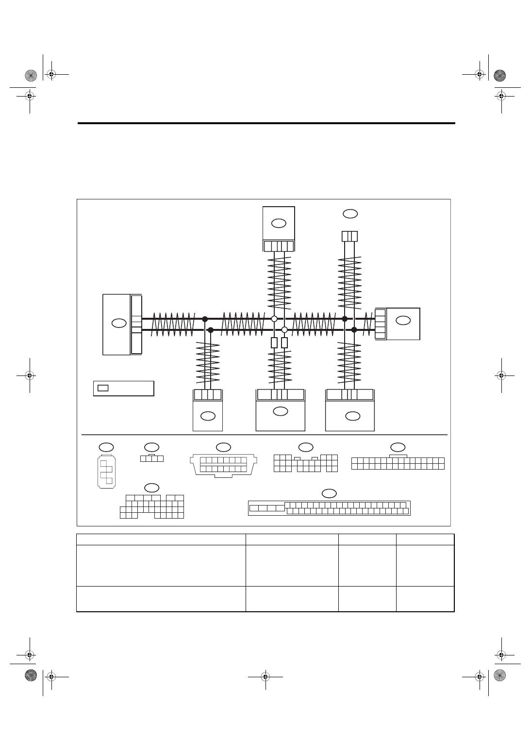
WIRING DIAGRAM:
CAN communication system <Ref. to WI-171, WIRING DIAGRAM, CAN Communication System.>
Step
Check
Yes
No
1
Is there DTC U1202?
Perform the diag-
nosis according to
DTC.
2
CHECK DTC.
Read the DTC of body integrated unit using
Subaru Select Monitor.
Is U1211 a current malfunc-
tion?
2
1
B231
1
8
2
B380
B3
B9
B280
B:
6
14
B40
B380
1 2 3 4
17 18 19 20
5 6 7 8
21 22 23 24
9 10 11 12
25 26 27 28
13 14 15 16
29 30 31 32
4 5 6 7 8 9
6
2
7
2
8
2
9
2
0
3
2 3
1
1
3
2
3
3
3
4
3
5
3
6
3
0
1
1
1
4
1
5
1
6
1
7
1
8
1
9
1
7
3
8
3
9
3
0
4
2
1
3
1
1
4
2
4
3
4
4
4
5
4
6
4
0
2
1
2
3
2
4
2
2
2
5
2
B310
B231
1 2 3 4
B230
1
2
3
4
C: B136
16
10 11 12 13 14 15
25
24
30
9
8
7
17 18 19 20
28
21 22 23
29
32
31
1
2
3
4
5
6
27
26
33 34 35
B280
B:
1 2 3
4 5 6
7 8 9 10 11 12 13 14 15 16 17
18 19 20
21 22 23 24
25 26
1 2 3 4 5 6 7 8
9 10 11 12 13 14 15 16
B40
C17
C28
C: B136
B230
3
2
B310
10
35
LAN00907
SI
SI
SI
VDC CM
ECM
DCCD CM
YAW RATE &
G SENSOR
: WITH SI-DRIVE
DATA LINK
CONNECTOR
BODY
INTEGRATED
UNIT
STEERING
ANGLE
SENSOR
LAN(diag)-52
Diagnostic Procedure with Diagnostic Trouble Code (DTC)
LAN SYSTEM (DIAGNOSTICS)
3
CHECK ECM.
1) Turn the ignition switch to OFF.
2) Disconnect the ECM connector.
3) Connect the disconnected connectors.
4) Turn the ignition switch to ON.
5) Read the DTC of body integrated unit using
Subaru Select Monitor.
Is U1211 a current malfunc-
tion?
4
CHECK HARNESS.
1) Turn the ignition switch to OFF.
2) Shake the harness used for CAN communi-
cation circuit.
3) Turn the ignition switch to ON.
4) Read the DTC of body integrated unit using
Subaru Select Monitor.
Is U1211 a current malfunc-
tion?
Repair the poor
contact or tempo-
rary open circuit of
harness.
5
CHECK CONNECTOR.
1) Turn the ignition switch to OFF.
2) Disconnect the connector that is connected
to high speed CAN circuit.
Is there poor contact of connec-
tor?
Repair the connec-
tor terminal where
poor contact
exists, or replace
harness.
It is possible that
temporary poor
communication
occurs.
Step
Check
Yes
No
Нет комментариевНе стесняйтесь поделиться с нами вашим ценным мнением.
Текст