Subaru Impreza 3 / Impreza WRX / Impreza WRX STI. Service manual — part 788
LAN(diag)-61
Diagnostic Procedure with Diagnostic Trouble Code (DTC)
LAN SYSTEM (DIAGNOSTICS)
3
CHECK DTC.
1) Turn the ignition switch to OFF.
2) Disconnect all control module connectors
(B280, B310, B136, B230, B231, B380) that are
connected to high speed CAN communication
line.
3) Connect the disconnected connectors.
4) Turn the ignition switch to ON.
5) Read the DTC of body integrated unit using
Subaru Select Monitor.
Is U1223 a current malfunc-
tion?
4
CHECK HARNESS.
1) Turn the ignition switch to OFF.
2) Disconnect all control module connectors
(B280, B310, B136, B230, B231, B380) that are
connected to high speed CAN communication
line.
3) Using the tester, check for open, short
(power supply-output short, GND-output short)
in the harness.
Connector & terminal
(B40) No. 6 — (B310) No. 35:
(B40) No. 14 — (B310) No. 10:
Is harness normal?
Repair or replace
the harness.
5
CHECK DTC.
1) Connect the disconnected connectors.
2) Start the engine and stop.
3) Turn the ignition switch to ON.
4) Read the DTC of body integrated unit using
Subaru Select Monitor.
Is U1223 a current malfunc-
tion?
6
CHECK DTC.
Read all DTCs using the Subaru Select Monitor.
Is U0122 displayed?
Replace the body
integrated unit.
<Ref. to SL-48,
REMOVAL, Body
Integrated Unit.>
7
CHECK HARNESS.
1) Shake the harness used for CAN communi-
cation circuit.
2) Read the DTC of body integrated unit using
Subaru Select Monitor.
Is U1223 a current malfunc-
tion?
Repair or replace
the harness.
8
CHECK CONNECTOR.
1) Turn the ignition switch to OFF.
2) Disconnect all control module connectors
(B280, B310, B136, B230, B231, B380) that are
connected to high speed CAN communication
line.
Is there connector terminal
where poor contact exists?
Repair the connec-
tor terminal where
poor contact
exists, or replace
harness.
Temporary poor
contact occurs.
Step
Check
Yes
No
LAN(diag)-62
Diagnostic Procedure with Diagnostic Trouble Code (DTC)
LAN SYSTEM (DIAGNOSTICS)
M: DTC U1226 HIGH-SPEED CAN (DCCD) DATA IS NOT RECEIVED
DTC DETECTING CONDITION:
Not received data from DCCD CM.
TROUBLE SYMPTOM:
DCCD indicator blinks.
WIRING DIAGRAM:
CAN communication system <Ref. to WI-171, WIRING DIAGRAM, CAN Communication System.>
Step
Check
Yes
No
1
Is there DTC U1202?
Perform the diag-
nosis according to
DTC.
2
CHECK DTC.
Read the DTC of body integrated unit using
Subaru Select Monitor.
Is U1226 a current malfunc-
tion?
2
1
B231
1
8
2
B380
B3
B9
B280
B:
6
14
B40
B380
1 2 3 4
17 18 19 20
5 6 7 8
21 22 23 24
9 10 11 12
25 26 27 28
13 14 15 16
29 30 31 32
4 5 6 7 8 9
6
2
7
2
8
2
9
2
0
3
2 3
1
1
3
2
3
3
3
4
3
5
3
6
3
0
1
1
1
4
1
5
1
6
1
7
1
8
1
9
1
7
3
8
3
9
3
0
4
2
1
3
1
1
4
2
4
3
4
4
4
5
4
6
4
0
2
1
2
3
2
4
2
2
2
5
2
B310
B231
1 2 3 4
B230
1
2
3
4
C: B136
16
10 11 12 13 14 15
25
24
30
9
8
7
17 18 19 20
28
21 22 23
29
32
31
1
2
3
4
5
6
27
26
33 34 35
B280
B:
1 2 3
4 5 6
7 8 9 10 11 12 13 14 15 16 17
18 19 20
21 22 23 24
25 26
1 2 3 4 5 6 7 8
9 10 11 12 13 14 15 16
B40
C17
C28
C: B136
B230
3
2
B310
10
35
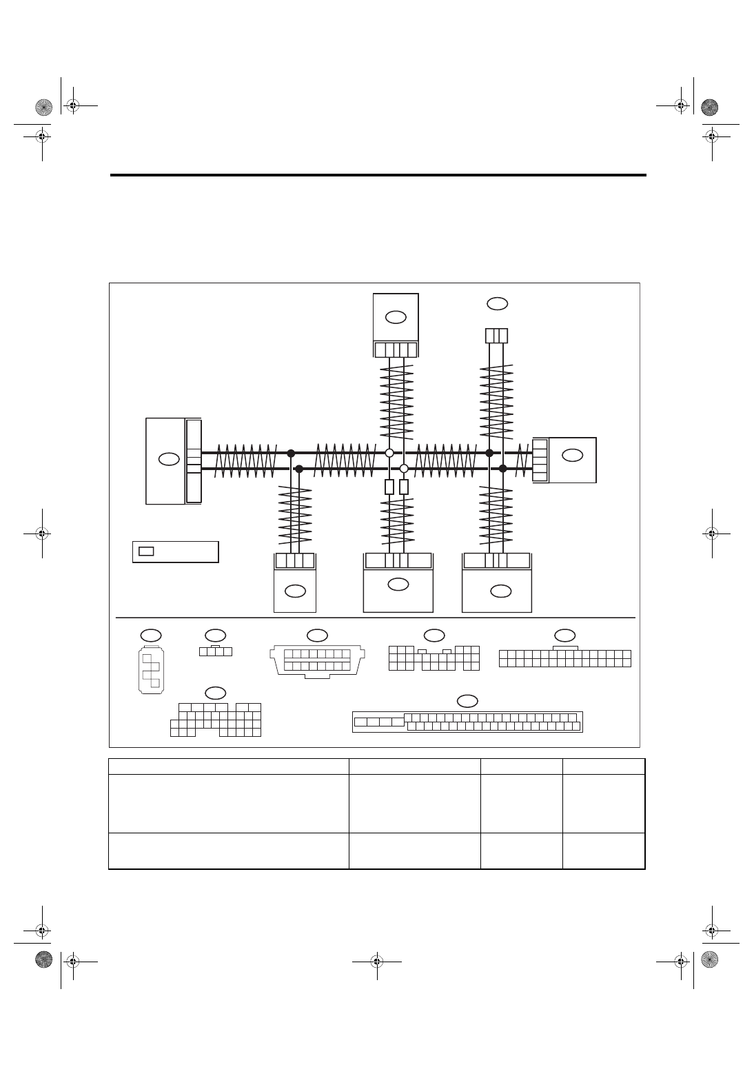
LAN00907
SI
SI
SI
VDC CM
ECM
DCCD CM
YAW RATE &
G SENSOR
: WITH SI-DRIVE
DATA LINK
CONNECTOR
BODY
INTEGRATED
UNIT
STEERING
ANGLE
SENSOR
LAN(diag)-63
Diagnostic Procedure with Diagnostic Trouble Code (DTC)
LAN SYSTEM (DIAGNOSTICS)
3
CHECK DTC.
1) Turn the ignition switch to OFF.
2) Disconnect all control module connectors
(B280, B310, B136, B230, B231, B380) that are
connected to high speed CAN communication
line.
3) Connect the disconnected connectors.
4) Turn the ignition switch to ON.
5) Read the DTC of body integrated unit using
Subaru Select Monitor.
Is U1226 a current malfunc-
tion?
4
CHECK HARNESS.
1) Turn the ignition switch to OFF.
2) Disconnect all control module connectors
(B280, B310, B136, B230, B231, B380) that are
connected to high speed CAN communication
line.
3) Using the tester, check for open, short
(power supply-output short, GND-output short)
in the harness.
Connector & terminal
(B380) No. 18 — (B40) No. 14:
(B380) No. 2 — (B40) No. 6:
Is harness normal?
Repair or replace
the harness.
5
CHECK DTC.
1) Connect the disconnected connectors.
2) Start the engine and stop.
3) Turn the ignition switch to ON.
4) Read the DTC of body integrated unit using
Subaru Select Monitor.
Is U1226 a current malfunc-
tion?
6
CHECK DCCD CM.
1) Turn the ignition switch to OFF.
2) Replace with a DCCD CM that is operating
normally.
3) Turn the ignition switch to ON.
4) Read the DTC of body integrated unit using
Subaru Select Monitor.
Is U1226 a current malfunc-
tion?
Replace the body
integrated unit.
<Ref. to SL-48,
REMOVAL, Body
Integrated Unit.>
7
CHECK HARNESS.
1) Shake the harness used for CAN communi-
cation circuit.
2) Read the DTC of body integrated unit using
Subaru Select Monitor.
Is U1226 a current malfunc-
tion?
Repair or replace
the harness.
8
CHECK CONNECTOR.
1) Turn the ignition switch to OFF.
2) Disconnect all the connector that is con-
nected to high speed CAN circuit.
Is there poor contact of connec-
tor terminal?
Repair the connec-
tor terminal where
poor contact
exists, or replace
harness.
Temporary com-
munication failure
occurs.
Step
Check
Yes
No
LAN(diag)-64
Diagnostic Procedure with Diagnostic Trouble Code (DTC)
LAN SYSTEM (DIAGNOSTICS)
N: DTC U1300 CAN-LS MALFUNCTION
DTC DETECTING CONDITION:
Open or short in low speed CAN circuit
TROUBLE SYMPTOM:
Low speed CAN communication can not be executed normally.
WIRING DIAGRAM:
CAN communication system <Ref. to WI-171, WIRING DIAGRAM, CAN Communication System.>
Step
Check
Yes
No
1
Is U1300 a current malfunc-
tion?
2
*
1
*
i84
1 2
3 4
5 6
7 8
9 10 11 12
14 15 16 17 18 19 20 21 22 23
24 25
26 27 28 29
30 31 32 33
34 35
13
i88
i10
1 2 3 4 5 6 7 8 9 10 11 12 13 14 15 16 17 18 19 20
21 22 23 24 25 26 27 28 29 30 31 32 33 34 35 36 37 38 39 40
i77
1 2 3 4 5 6 7 8 9 10
i85
1 2 3 4 5 6 7 8 9
10 11 12 13 14 15 16 17 18 19 20
2
*
2
*
2
*
2
*
1
*
1
*
1
*
1
*
11
12
AA
AA
AA
20
i85
i88
19
27
i10
26
i77
i84
1
9
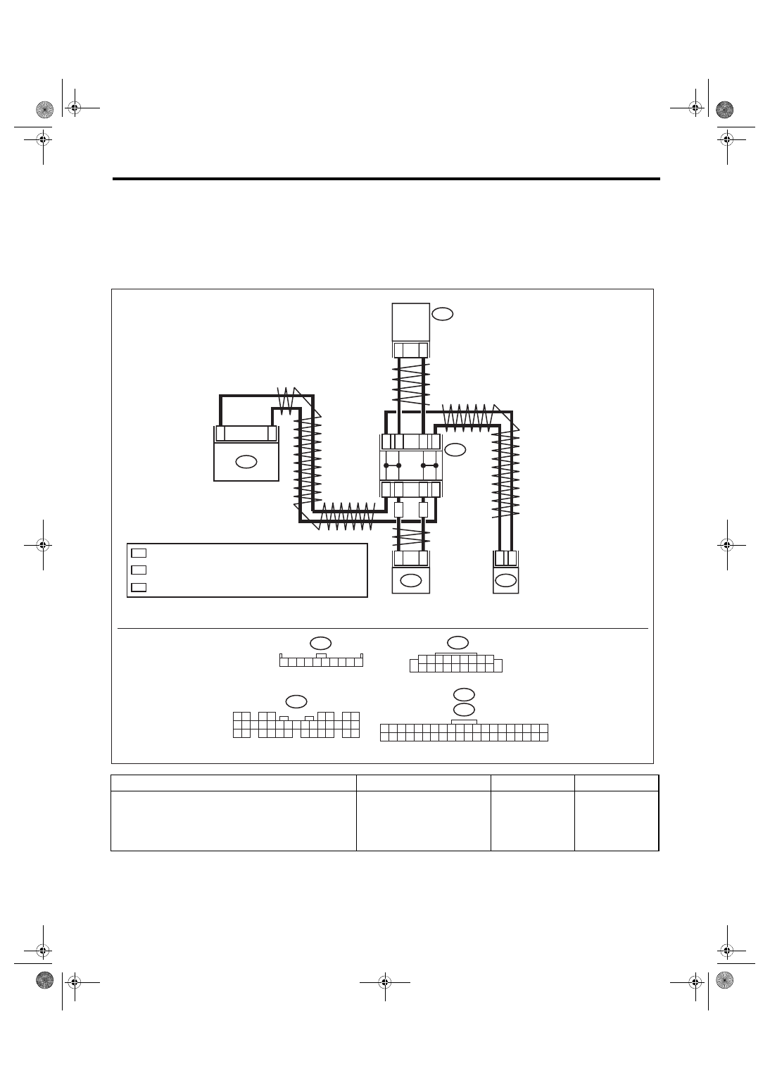
LAN01360
BODY
INTEGRATED
UNIT
CAN JOINT
CONNECT
OR
COMBINATION
METER
AUDIO
: AUTO A/C
A/C
CONTROL
PANEL
: TERMINAL No. OPTIONAL ARRANGEMENT AMONG 1, 2, 3, 4 AND 5
: TERMINAL No. OPTIONAL ARRANGEMENT AMONG 6, 7, 8, 9 AND 10
Нет комментариевНе стесняйтесь поделиться с нами вашим ценным мнением.
Текст