Subaru Impreza 3 / Impreza WRX / Impreza WRX STI. Service manual — part 782

LAN(diag)-37
Diagnostic Procedure with Diagnostic Trouble Code (DTC)
LAN SYSTEM (DIAGNOSTICS)
Step
Check
Yes
No
1
Is B1101 current malfunction? Go to step
2
CHECK DTC.
1) Turn the ignition switch to OFF.
2) Disconnect the connector from body inte-
grated unit and reconnect.
3) Wait approx. 2 minutes.
4) Turn the ignition switch to ON.
5) Read the DTC of body integrated unit using
Subaru Select Monitor.
Is B1101 current malfunction? Go to step
3
CHECK FUSE.
1) Turn the ignition switch to OFF.
2) Check the fuse.
Is the fuse OK?
Replace the defec-
tive fuse.
4
CHECK HARNESS.
1) Disconnect the body integrated unit connec-
tor (B280).
2) Measure the voltage between body inte-
grated unit connector and chassis ground using
tester.
Connector & terminal
(B280) No. 6 (+) — Chassis ground (–):
Is the voltage 8.5 — 16.5 V?
Replace the body
integrated unit.
<Ref. to SL-48,
REMOVAL, Body
Integrated Unit.>
Repair or replace
the open or
shorted circuit
between body inte-
grated unit and
fuse.
5
CHECK CONNECTOR.
1) Turn the ignition switch to OFF.
2) Disconnect the body integrated unit connec-
tor (B280).
Is there poor contact of connec-
tor?
Repair or replace
the poor contact of
connector.
A temporary
change of voltage
occurred.
LAN(diag)-38
Diagnostic Procedure with Diagnostic Trouble Code (DTC)
LAN SYSTEM (DIAGNOSTICS)
C: DTC B1102 BATT P/SUPPLY MALFUNCTION BACKUP
DTC DETECTING CONDITION:
• Open or short of battery power supply backup circuit
• Voltage malfunction caused by poor contact
TROUBLE SYMPTOM:
No influence.
NOTE:
• When B1101 BATT P/SUPPLY MALFUNCTION CONT. is output at the same time, all function of body in-
tegrated unit may not operate.
• B1101 may input when the battery run-out occurs.
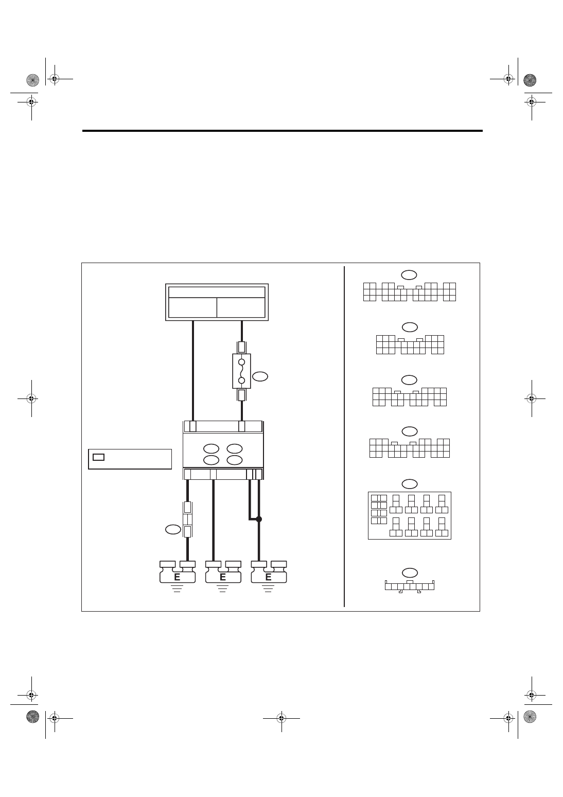
WIRING DIAGRAM:
CAN communication system <Ref. to WI-171, WIRING DIAGRAM, CAN Communication System.>
i97
2 3 4 5
1
6 7 8
13
14
15 16
17
27
24
25
26
20
21
22
23
29
30
31
28
32 35
33
34
37
38
39
36
40
8
9
10
11 12
1
2
5
3
4
7
6
19
18
B225
*
1
*
1
*
1
B225
3
4
10A
C20
B17
D27
B279
D:
B281
C:
B280
B:
i84
A:
C2
B6
i97
A2
8
B279
D:
5
7
6
4
8
2
1
9
3
10
23
2
2
11 12 13 14 15
27
6
2
5
2
4
2
16 17 18
29
8
2
19 20
21
30
B280
B:
6
4 5
3
1 2
9
7 8
17
6
1
5
1
4
1
3
1
2
1
1
1
0
1
20
9
1
8
1
24
3
2
2
2
1
2
26
5
2
7
5 6
8
2
1
9
4
3
0
1
4
2
2
2
5
2
3
2
1
1
2
1
3
1
4
1
5
1
8
2
7
2
6
2
6
1
7
1
8
1
9
1
1
2
0
2
B281
C:
1 2
3 4
5 6
7 8
9 0
1
1
1
2
1
4
1
5
1
6
1
7
1
8
1
9
1
0
2
1
2
2
2
3
2
4
2
5
2
6
2
7
2
8
2
9
2
0
3
1
3
2
3
3
3
4
3
5
3
3
1
A:
LAN00604
i84
JOINT GROUND
CONNECTOR
BODY INTEGRATED UNIT
FB-18
F/B FUSE NO. 7
(B)
MB-29
M/B FUSE NO. 8
(B)
TO POWER SUPPLY CIRCUIT
FUSE
(RELAY BLOCK)
: TERMINAL No. OPTIONAL
ARRANGEMENT
RELAY BLOCK

LAN(diag)-39
Diagnostic Procedure with Diagnostic Trouble Code (DTC)
LAN SYSTEM (DIAGNOSTICS)
Step
Check
Yes
No
1
Is B1102 current malfunction? Go to step
2
CHECK DTC.
1) Turn the ignition switch to OFF.
2) Disconnect the connector from body inte-
grated unit and reconnect.
3) Wait approx. 2 minutes.
4) Turn the ignition switch to ON.
5) Read the DTC of body integrated unit using
Subaru Select Monitor.
Is B1102 current malfunction? Go to step
3
CHECK FUSE.
1) Turn the ignition switch to OFF.
2) Check the fuse.
Is the fuse OK?
Replace the defec-
tive fuse.
4
CHECK HARNESS.
1) Disconnect the body integrated unit connec-
tor (B281).
2) Measure the voltage between body inte-
grated unit connector and chassis ground using
tester.
Connector & terminal
(B281) No. 2 (+) — Chassis ground (–):
Is the voltage 8.5 — 16.5 V?
Replace the body
integrated unit.
<Ref. to SL-48,
REMOVAL, Body
Integrated Unit.>
Repair or replace
the open or
shorted circuit
between body inte-
grated unit and
fuse.
5
CHECK CONNECTOR.
1) Turn the ignition switch to OFF.
2) Disconnect the body integrated unit connec-
tor (B281).
Is there poor contact of connec-
tor?
Repair or replace
the poor contact of
connector.
A temporary
change of voltage
occurred.
LAN(diag)-40
Diagnostic Procedure with Diagnostic Trouble Code (DTC)
LAN SYSTEM (DIAGNOSTICS)
D: DTC B1103 IGNITION POWER FAILURE
DTC DETECTING CONDITION:
• Open or short in IGN power supply circuit
• Voltage malfunction caused by poor contact
TROUBLE SYMPTOM:
Error related to LAN system will not be detected.
NOTE:
B1103 may output when the ignition switch turns to ON with the weak battery condition.
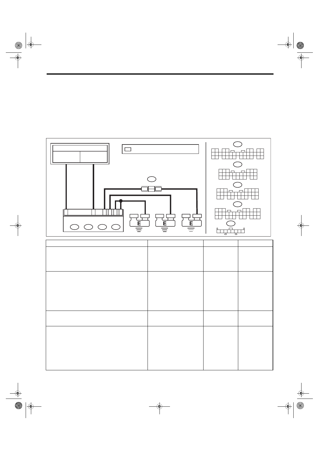
WIRING DIAGRAM:
Headlight System <Ref. to WI-90, WIRING DIAGRAM, Headlight System.>
Step
Check
Yes
No
1
Is B1103 current malfunction? Go to step
2
CHECK DTC.
1) Turn the ignition switch to OFF.
2) Disconnect the connector from body inte-
grated unit and reconnect.
3) Turn the ignition switch to ON.
4) Wait approx. 2 minutes.
5) Read the DTC of body integrated unit using
Subaru Select Monitor.
Is B1103 current malfunction? Go to step
3
CHECK FUSE.
1) Turn the ignition switch to OFF.
2) Check the fuse.
Is the fuse OK?
Replace the defec-
tive fuse.
4
CHECK HARNESS.
1) Disconnect the body integrated unit connec-
tor (B280).
2) Turn the ignition switch to ON.
3) Measure the voltage between body inte-
grated unit connector and chassis ground using
tester.
Connector & terminal
(B280) No. 1 (+) — Chassis ground (–):
Is the voltage 8.5 — 16.5 V?
Replace the body
integrated unit.
<Ref. to SL-48,
REMOVAL, Body
Integrated Unit.>
Repair or replace
the open or
shorted circuit
between body inte-
grated unit and
fuse.
i97
2 3 4 5
1
6 7 8
*
1
*
1
*
1
i97
i84
A:
B1
A: i84
1 2
3 4
5 6
7 8
9 10 11 12
14 15 16 17 18 19 20 21 22 23
24 25
26 27 28 29
30 31 32 33
34 35
13
A2
8
B7
B280
B:
6
4 5
3
1 2
9
7 8
17
6
1
5
1
4
1
3
1
2
1
1
1
0
1
20
9
1
8
1
24
3
2
2
2
1
2
26
5
2
D27
B17
C20
5
7
6
4
8
2
1
9
3
0
1
3
2
2
2
1
1
2
1
3
1
4
1
5
1
7
2
6
2
5
2
4
2
6
1
7
1
8
1
9
2
8
2
9
1
0
2
21
30
B279
D:
7
5 6
8
2
1
9
4
3
0
1
4
2
5
2
3
2
2
2
1
1
2
1
3
1
4
1
5
1
8
2
7
2
6
2
6
1
7
1
8
1
9
1
1
2
0
2
B281
C:
D: B279
B: B280 C: B281
LAN00605
TO POWER SUPPLY CIRCUIT
BODY INTEGRATED UNIT
FB-38
F/B FUSE NO. 12
(IG)
FB-29
F/B FUSE NO. 31
(ACC)
JOINT GROUND CONNECTOR
: TERMINAL No. OPTIONAL ARRANGEMENT
Нет комментариевНе стесняйтесь поделиться с нами вашим ценным мнением.
Текст