Subaru Impreza 3 / Impreza WRX / Impreza WRX STI. Service manual — part 336
GD(H4DOTC)-96
Diagnostic Trouble Code (DTC) Detecting Criteria
GENERAL DESCRIPTION
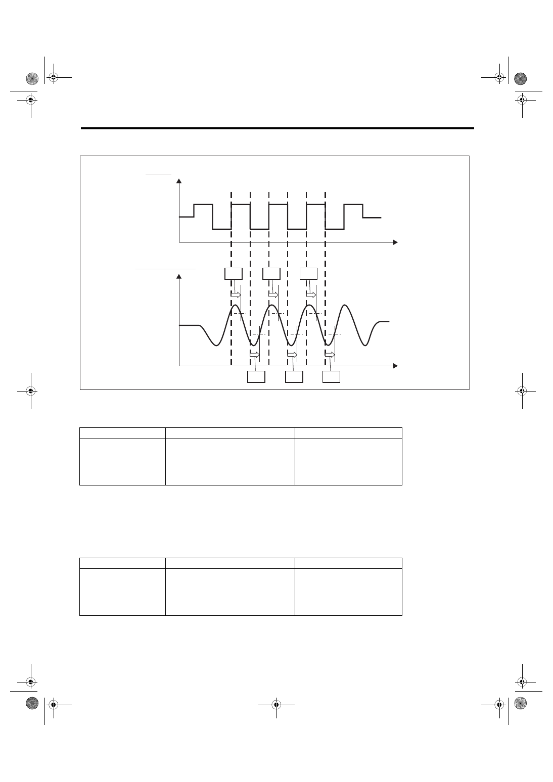
Measure reaction time (t1, t2, t3) and reaction time (t4, t5, t6). Use the average value of the reaction time to
obtain the diagnostic value.
• Abnormality Judgment
Judge as NG when the following conditions are established.
Time Needed for Diagnosis: 1000 ms × [1 time(s)/2] + 1000 ms × 3 time(s) + 500 ms
Malfunction Indicator Light Illumination: Illuminates when malfunction occurs in 2 continuous driving cy-
cles.
• Normality Judgment
Judge as OK and clear the NG if the following conditions are established.
Time Needed for Diagnosis: 1000 ms × [1 time(s)/2] + 1000 ms × 3 time(s) + 500 ms
Judgment Value
Malfunction Criteria
Threshold Value
DTC
(t1 + t2 + t3)/3
> 420 ms (Models without SI-DRIVE)
> 380 ms (Models with SI-DRIVE)
P015A and P015B
and
(t4 + t5 + t6)/3
> 420 ms (Models without SI-DRIVE)
> 380 ms (Models with SI-DRIVE)
Judgment Value
Malfunction Criteria
Threshold Value
DTC
(t1 + t2 + t3)/3
≤ 420 ms (Models without SI-DRIVE)
≤ 380 ms (Models with SI-DRIVE)
P015A and P015B
or
(t4 + t5 + t6)/3
≤ 420 ms (Models without SI-DRIVE)
≤ 380 ms (Models with SI-DRIVE)
EN-09891
Time
Lean
Rich
Lean
Rich
STFT
Time
Sensor output
t1
t2
t3
t4
t5
t6
GD(H4DOTC)-97
Diagnostic Trouble Code (DTC) Detecting Criteria
GENERAL DESCRIPTION
AZ:DTC P015B O2 SENSOR DELAYED RESPONSE - LEAN TO RICH (BANK 1
SENSOR 1)
1. OUTLINE OF DIAGNOSIS
NOTE:
For the detection standard, refer to DTC P015A. <Ref. to GD(H4DOTC)-91, DTC P015A O2 SENSOR DE-
LAYED RESPONSE - RICH TO LEAN (BANK 1 SENSOR 1), Diagnostic Trouble Code (DTC) Detecting Cri-

GD(H4DOTC)-98
Diagnostic Trouble Code (DTC) Detecting Criteria
GENERAL DESCRIPTION
BA:DTC P0171 SYSTEM TOO LEAN (BANK 1)
1. OUTLINE OF DIAGNOSIS
Detect fuel system malfunction by the amount of main feedback control.
Diagnostic method
Fuel system is diagnosed by comparing the target air fuel ratio calculated by ECM with the actual air fuel ratio
measured by sensor.
2. ENABLE CONDITIONS
3. GENERAL DRIVING CYCLE
Perform the diagnosis continuously at idling or at a constant speed after warming up the engine.
4. DIAGNOSTIC METHOD
• Abnormality Judgment
Compare the diagnostic value (fsobd) with the threshold value, and if a condition meeting the malfunction cri-
teria below continues for 10 s × 3 time(s) or more, judge that there is a fault in the fuel system.
Time Needed for Diagnosis: 10 s × 3 time(s)
Malfunction Indicator Light Illumination: Illuminates when malfunction occurs in 2 continuous driving cy-
cles.
• Normality Judgment
Judge as OK and clear the NG if the continuous time while the following conditions are established is more
than the predetermined time.
Time Needed for Diagnosis: 10 s
Secondary Parameters
Enable Conditions
A/F main learning system
In operation
Engine load change
< 0.02 g/rev (0 oz/rev)
Engine load
≥ Value of Map 1
Map 1
Engine speed (rpm)
Idling
650
1000
1500
2000
2500
3000
3500
4000
4500
Measured value (g (oz)/rev)
na
0 (0)
0 (0)
0 (0)
0 (0)
0 (0)
0 (0)
0 (0)
0 (0)
0 (0)
Judgment Value
Malfunction Criteria
Threshold Value
fsobd = (sglmd – tglmda) + faf + flaf
≥ Value from Map 2
In this case: sglmd = measured lambda
tglmda = target lambda
faf = main feedback compensation coefficient (every 64 milliseconds)
flaf = main feedback learning compensation coefficient
Map 2
Amount of air (g (oz)/s)
0 (0)
3.2
(0.11)
6.4
(0.23)
9.6
(0.34)
12.8
(0.45)
16
(0.56)
19.2
(0.68)
fsobdL1 (%)
1.35
1.35
1.35
1.35
1.35
1.35
1.35
Judgment Value
Malfunction Criteria
Threshold Value
fsobd = (sglmd – tglmda) + faf + flaf
< 1.15

GD(H4DOTC)-99
Diagnostic Trouble Code (DTC) Detecting Criteria
GENERAL DESCRIPTION
BB:DTC P0172 SYSTEM TOO RICH (BANK 1)
1. OUTLINE OF DIAGNOSIS
Detect fuel system malfunction by the amount of main feedback control.
Diagnostic method
Fuel system is diagnosed by comparing the target air fuel ratio calculated by ECM with the actual air fuel ratio
measured by sensor.
2. ENABLE CONDITIONS
3. GENERAL DRIVING CYCLE
Perform the diagnosis continuously at idling or at a constant speed after warming up the engine.
4. DIAGNOSTIC METHOD
• Abnormality Judgment
Compare the diagnostic value (fsobd) with the threshold value, and if a condition meeting the malfunction cri-
teria below continues for 10 s × 3 time(s) or more, judge that there is a fault in the fuel system.
Time Needed for Diagnosis: 10 s × 3 time(s)
Malfunction Indicator Light Illumination: Illuminates when malfunction occurs in 2 continuous driving cy-
cles.
• Normality Judgment
Judge as OK if the status that the criteria below are met continues for 10 seconds.
Time Needed for Diagnosis: 10 s
Secondary Parameters
Enable Conditions
A/F main learning system
In operation
Engine load change
≤ 0.02 g/rev (0 oz/rev)
Learning value of EVAP conc.
< 1
Cumulative time of canister purge after engine start
≥ 0 s
Continuous period after canister purge starting
≥ 0 ms
Engine load
≥ Value of Map 1
Map 1
Engine speed (rpm)
Idling
650
1000
1500
2000
2500
3000
3500
4000
4500
Measured value (g (oz)/rev)
na
0 (0)
0 (0)
0 (0)
0 (0)
0 (0)
0 (0)
0 (0)
0 (0)
0 (0)
Judgment Value
Malfunction Criteria
Threshold Value
fsobd = (sglmd – tglmda) + faf + flaf
< Value of Map 2
In this case: sglmd = measured lambda
tglmda = target lambda
faf = main feedback compensation coefficient (every 64 milliseconds)
flaf = main feedback learning compensation coefficient
Map 2
Amount of air (g (oz)/s)
0 (0)
3.2
(0.11)
6.4
(0.23)
9.6
(0.34)
12.8
(0.45)
16
(0.56)
19.2
(0.68)
fsobdL1 (%)
0.65
0.65
0.65
0.65
0.65
0.65
0.65
Judgment Value
Malfunction Criteria
Threshold Value
fsobd = (sglmd – tglmda) + faf + flaf
≥ 0.85
Нет комментариевНе стесняйтесь поделиться с нами вашим ценным мнением.
Текст