Subaru Impreza 3 / Impreza WRX / Impreza WRX STI. Service manual — part 103
LU(STI)-14
Oil Pump
LUBRICATION
B: INSTALLATION
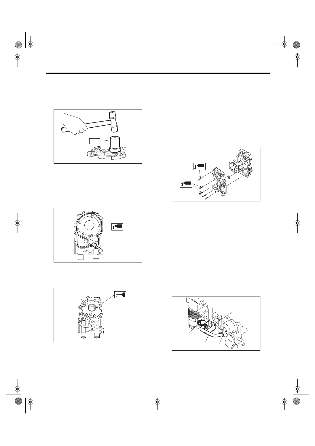
1) Using the ST, install the front oil seal.
ST 499587100
OIL SEAL INSTALLER
NOTE:
Use a new front oil seal.
2) Apply liquid gasket to the mating surfaces of oil
pump.
NOTE:
Install within 5 min. after applying liquid gasket.
Liquid gasket:
THREE BOND 1217G (Part No. K0877Y0100)
or equivalent
3) Apply a coat of engine oil to the inside of front oil
seal.
4) Install the oil pump to cylinder block.
CAUTION:
• Be careful not to damage the front oil seal
during installation.
• Make sure the front oil seal lip is not folded.
NOTE:
• Align the flat surface of oil pump’s inner rotor with
that of crankshaft before installation.
• Use new O-rings.
• Do not forget to install O-rings.
5) Apply liquid gasket to the three bolts thread
shown in figure. (when reusing bolts)
Liquid gasket:
THREE BOND 1324 (Part No. 004403042) or
equivalent
Tightening torque:
6.4 N·m (0.7 kgf-m, 4.7 ft-lb)
6) Install the crank sprocket. <Ref. to ME(STI)-60,
INSTALLATION, Crank Sprocket.> <Ref. to ME(w/
o STI)-58, INSTALLATION, Crank Sprocket.>
7) Install the water pump. <Ref. to CO(STI)-15, IN-
STALLATION, Water Pump.> <Ref. to CO(w/o
STI)-15, INSTALLATION, Water Pump.>
8) Install the crankshaft position sensor. <Ref. to
FU(STI)-35, INSTALLATION, Crankshaft Position
Sensor.> <Ref. to FU(w/o STI)-35, INSTALLA-
TION, Crankshaft Position Sensor.>
9) Lift up the vehicle.
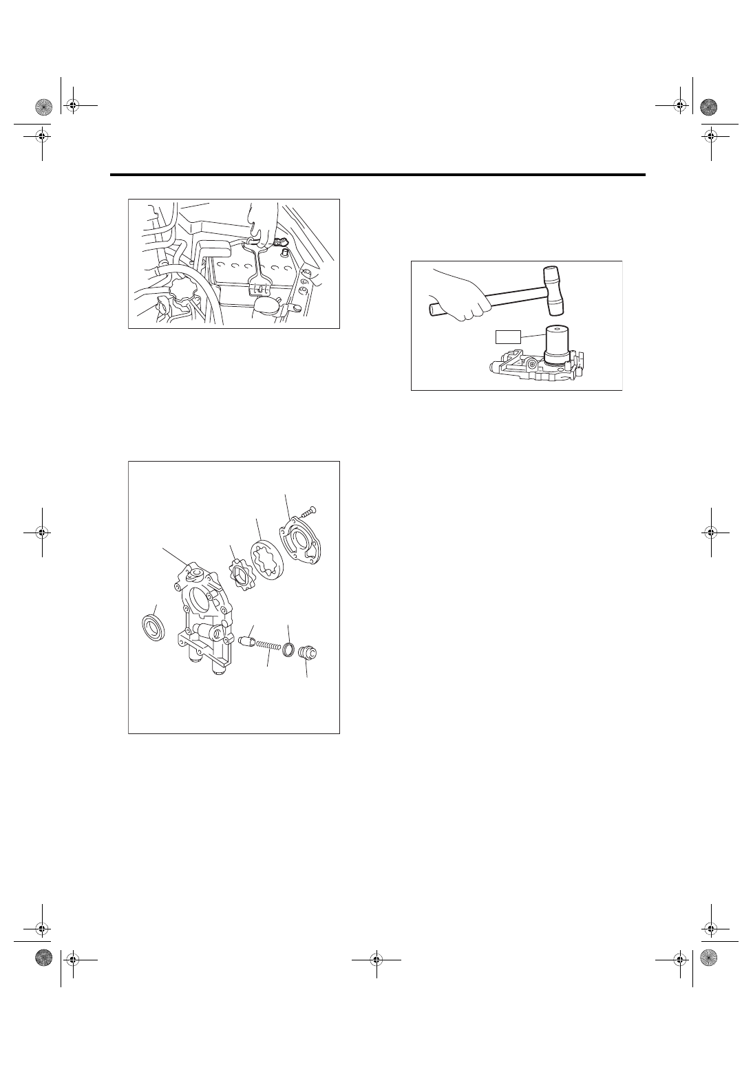
10) Install oil cooler pipe (A) and hose (C). (Model
with oil cooler)
11) Install the oil cooler pipe (A) to oil pump using
the bolts (B). (Model with oil cooler)
Tightening torque:
6.4 N·m (0.7 kgf-m, 4.7 ft-lb)
12) Lower the vehicle.
13) Install the radiator. <Ref. to CO(STI)-20, IN-
STALLATION, Radiator.> <Ref. to CO(w/o STI)-
(A) O-ring
LU-00021
ST
ME-00165
(A)
ME-00312
ME-04946
LU-02396
(B)
(C)
(C)
(A)
LU(STI)-15
Oil Pump
LUBRICATION
14) Connect the battery ground terminal.
C: DISASSEMBLY
Remove the screw which secures oil pump cover
and then disassemble oil pump. Inscribe alignment
marks on the inner rotor and outer rotor so that they
can be replaced in their original positions during re-
assembly.
NOTE:
Before disassembling the oil pump, remove the re-
lief valve.
D: ASSEMBLY
1) Using the ST, install the front oil seal.
ST 499587100
OIL SEAL INSTALLER
NOTE:
Use a new front oil seal.
2) Apply a coat of engine oil to the inner rotor and
outer rotor.
3) Install the inner rotor and outer rotor.
4) Assemble the oil relief valve and install relief
valve spring and plug.
NOTE:
Use a new gasket.
(A) Front oil seal
(B) Oil pump case
(C) Inner rotor
(D) Outer rotor
(E) Oil pump cover
(F) Relief valve
(G) Relief valve spring
(H) Plug
(I) Gasket
IN-00203
LU-00020
(E)
(D)
(C)
(B)
(A)
(F)
(G)
(I)
(H)
LU-00021
ST
LU(STI)-16
Oil Pump
LUBRICATION
5) Install the oil pump cover.
Tightening torque:
T1: 5.4 N·m (0.6 kgf-m, 4.0 ft-lb)
T2: 44 N·m (4.5 kgf-m, 32.5 ft-lb)
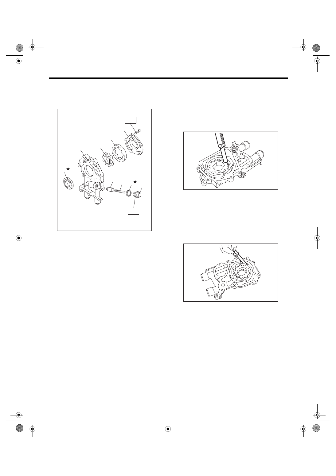
E: INSPECTION
1. TIP CLEARANCE
Measure the tip clearance of rotors. If the clearance
is out of standard, replace the rotors as a set.
Tip clearance between inner and outer rotors:
Standard
0.04 — 0.14 mm (0.0016 — 0.0055 in)
2. CASE CLEARANCE
Measure the clearance between outer rotor and oil
pump case. If clearance exceeds the standard, re-
place the oil pump case.
Case clearance between outer rotor and pump
case:
Standard
0.10 — 0.175 mm (0.0039 — 0.0069 in)
(A) Front oil seal
(B) Oil pump case
(C) Inner rotor
(D) Outer rotor
(E) Oil pump cover
(F) Relief valve
(G) Relief valve spring
(H) Plug
(I) Gasket
LU-02134
T1
T2
(G)
(F)
(I)
(H)
(A)
(B)
(C)
(D)
(E)
LU-00023
LU-00024
LU(STI)-17
Oil Pump
LUBRICATION
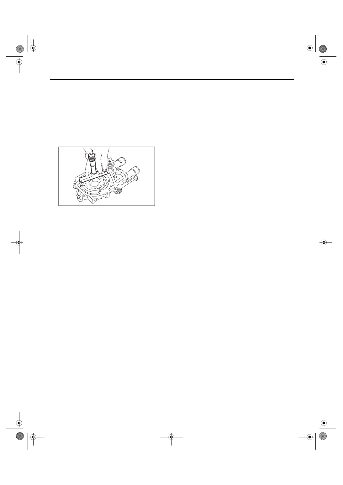
3. SIDE CLEARANCE
Measure the gap between the inner rotor and the
oil pump case to measure the clearance between
the inner rotor and the oil pump cover as shown in
the figure. If clearance is out of standard, replace
the rotor or the oil pump case.
Side clearance between inner rotor and pump
case:
Standard
0.02 — 0.07 mm (0.0008 — 0.0028 in)
4. OIL RELIEF VALVE
Check the valve for assembly condition and dam-
age, and the relief valve spring for damage and de-
terioration.
Replace the parts if defective.
Relief valve spring:
Free length
73.7 mm (2.902 in)
Installed length
54.7 mm (2.154 in)
Load when installed
93.1 N (9.49 kgf, 20.93 lbf)
5. OIL PUMP CASE
Check for worn shaft hole, clogged oil passage,
worn rotor chamber, cracks and other faults.
6. FRONT OIL SEAL
Check the front oil seal lips for deformation, hard-
ening, wear, etc. and replace if defective.
LU-00025
Нет комментариевНе стесняйтесь поделиться с нами вашим ценным мнением.
Текст