Subaru Impreza 3 / Impreza WRX / Impreza WRX STI. Service manual — part 293

EN(H4DOTC)(diag)-396
Diagnostic Procedure with Diagnostic Trouble Code (DTC)
ENGINE (DIAGNOSTICS)
2
CHECK HARNESS BETWEEN ECM AND
FRONT OXYGEN (A/F) SENSOR CONNEC-
TOR.
1) Turn the ignition switch to OFF.
2) Disconnect the connectors from ECM and
front oxygen (A/F) sensor.
3) Measure the resistance of harness between
ECM connector and front oxygen (A/F) sensor
connector.
Connector & terminal
Models without SI-DRIVE
(B136) No. 19 — (E22) No. 1:
(B136) No. 18 — (E22) No. 3:
Models with SI-DRIVE
(B136) No. 19 — (B379) No. 4:
(B136) No. 18 — (B379) No. 3:
Is the resistance less than 1 Ω? Go to step
Repair the open
circuit of harness
between ECM con-
nector and front
oxygen (A/F) sen-
sor connector.
3
CHECK FOR POOR CONTACT.
Check for poor contact of the front oxygen (A/F)
sensor connector.
Is there poor contact of front
oxygen (A/F) sensor connec-
tor?
Repair the poor
contact of front
oxygen (A/F) sen-
sor connector.
Step
Check
Yes
No
EN(H4DOTC)(diag)-397
Diagnostic Procedure with Diagnostic Trouble Code (DTC)
ENGINE (DIAGNOSTICS)
EY:DTC P2196 O2 SENSOR SIGNAL BIASED/STUCK RICH (BANK 1 SENSOR 1)
DTC DETECTING CONDITION:
• Detected when 2 consecutive driving cycles with fault occur.
• GENERAL DESCRIPTION <Ref. to GD(H4DOTC)-269, DTC P2196 O2 SENSOR SIGNAL BIASED/
STUCK RICH (BANK 1 SENSOR 1), Diagnostic Trouble Code (DTC) Detecting Criteria.>
CAUTION:
After servicing or replacing faulty parts, perform Clear Memory Mode <Ref. to EN(H4DOTC)(diag)-63,
OPERATION, Clear Memory Mode.>, and Inspection Mode <Ref. to EN(H4DOTC)(diag)-49, PROCE-
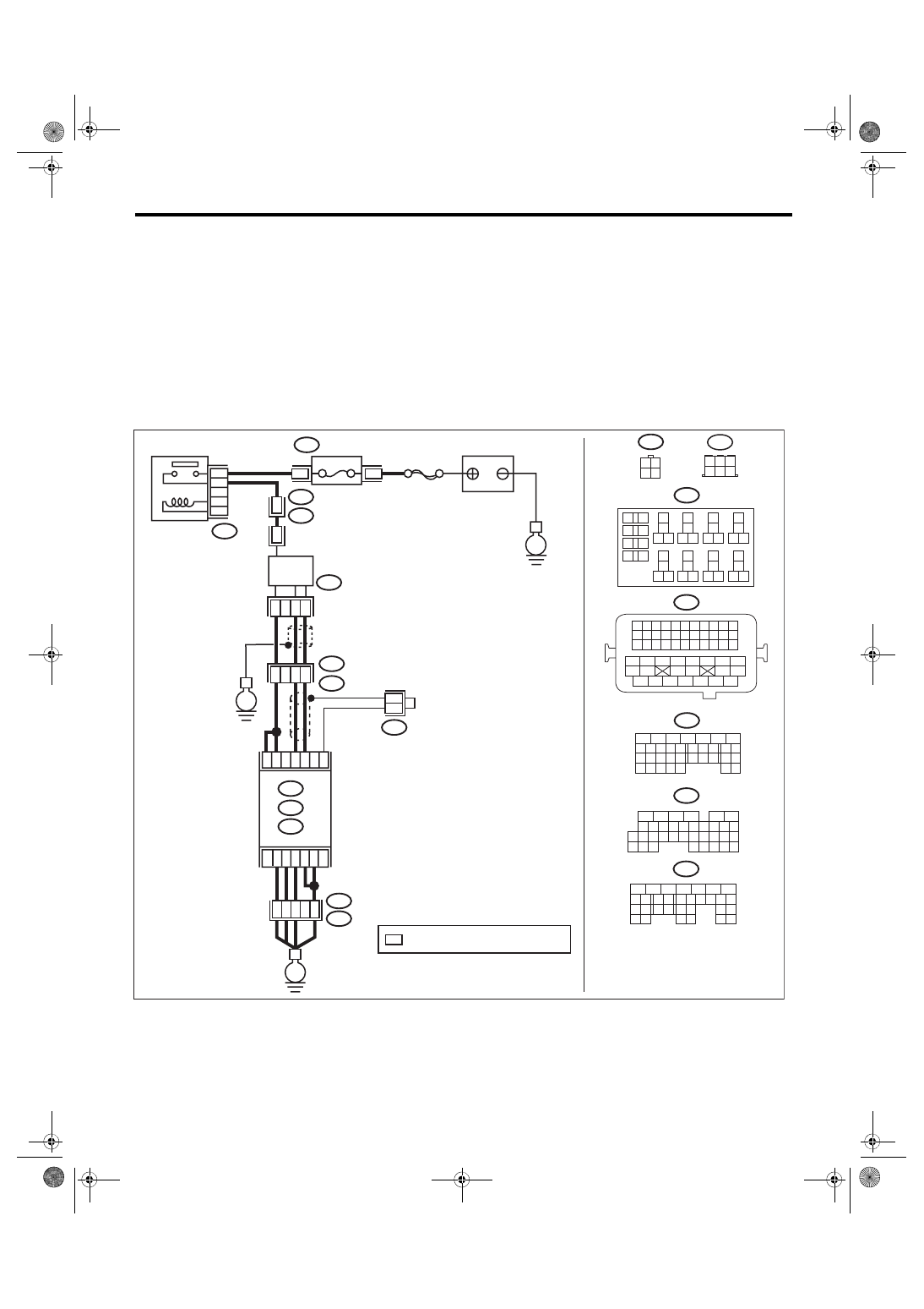
WIRING DIAGRAM:
• Models without SI-DRIVE <Ref. to WI-32, WITHOUT SI-DRIVE, WIRING DIAGRAM, Engine Electrical
ECM
B138
6
4 5
3
2
1
E22
1
2
3
15
43
26
B21
E2
44
2
E2
B21
1 2
3 4
E22
B220
13
14
15 16
17
27
24
25
26
20
21
22
23
29
30
31
28
32 35
33
34
37
38
39
36
40
8
9
10
11 12
1
2
5
3
4
7
6
19
18
2
1
B220
15A
9
10
11
12
B220
D:
5
6
7
8
2
1
9
4
3
10
22 23
11 12 13 14 15
24 25
26
16 17
18 19 20 21
27
28 29
30 31
B137
C: B136
16
10 11 12 13 14 15
25
24
30
9
8
7
17 18 19 20
28
21 22 23
29
32
31
1
2
3
4
5
6
27
26
33 34 35
*
*
*
B138
D1
36
A4
40
34
35
B21
E2
D3
A6
A3
A:
54
52 53
50 51
48 49
46 47
45
44
42 43
40 41
38 39
36 37
34 35
33
32
31
30
29
28
27
26
25
24
23
22
21
20
11
10
9
19
18
17
16
8
7
6
5
15
14
13
12
4
3
2
1
D: B137
C: B136
A:
31
30
32
29
34
33
21
20
19
18
17
16
28
27
26
15
14
13
12
11
25
23
22
24
10
3
4
9
1
2
8
7
6
5
B134
B21
B134
C9
C19
C1
8
C6
C5
EN-08720
E
E
E
SBF-5
BATTERY
: TERMINAL No. OPTIONAL ARRANGEMENT
A/F, OXYGEN SENSOR
RELAY
FUSE
(RELAY BLOCK)
FRONT OXYGEN (A/F)
SENSOR
EN(H4DOTC)(diag)-398
Diagnostic Procedure with Diagnostic Trouble Code (DTC)
ENGINE (DIAGNOSTICS)
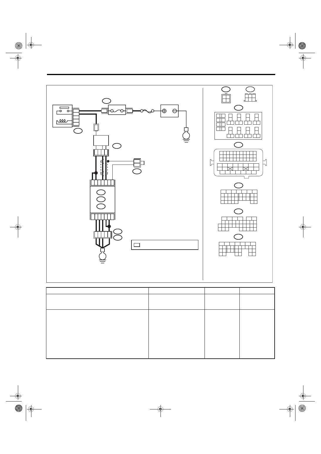
• Models with SI-DRIVE <Ref. to WI-48, WITH SI-DRIVE, WIRING DIAGRAM, Engine Electrical System.>
Step
Check
Yes
No
1
CHECK FRONT OXYGEN (A/F) SENSOR
CONNECTOR AND COUPLING CONNEC-
TOR.
Has water entered the connec-
tor?
Completely
remove any water
inside.
2
CHECK HARNESS BETWEEN ECM AND
FRONT OXYGEN (A/F) SENSOR CONNEC-
TOR.
1) Turn the ignition switch to OFF.
2) Disconnect the connector from ECM.
3) Measure the resistance between ECM con-
nector and chassis ground.
Connector & terminal
(B136) No. 19 — Chassis ground:
(B136) No. 18 — Chassis ground:
Is the resistance 1 MΩ or
more?
Repair the short
circuit to ground in
harness between
ECM connector
and front oxygen
(A/F) sensor con-
nector.
ECM
B138
6
4 5
3
2
1
1
2
3
4
B220
13
14
15 16
17
27
24
25
26
20
21
22
23
29
30
31
28
32 35
33
34
37
38
39
36
40
8
9
10
11 12
1
2
5
3
4
7
6
19
18
2
1
B220
15A
9
10
11
12
B220
D:
5
6
7
8
2
1
9
4
3
10
22 23
11 12 13 14 15
24 25
26
16 17
18 19 20 21
27
28 29
30 31
B137
C: B136
16
10 11 12 13 14 15
25
24
30
9
8
7
17 18 19 20
28
21 22 23
29
32
31
1
2
3
4
5
6
27
26
33 34 35
*
*
*
B138
D1
36
D3
A4
40
34
35
B21
E2
A6
A3
A:
54
52 53
50 51
48 49
46 47
45
44
42 43
40 41
38 39
36 37
34 35
33
32
31
30
29
28
27
26
25
24
23
22
21
20
11
10
9
19
18
17
16
8
7
6
5
15
14
13
12
4
3
2
1
D: B137
C: B136
A:
31
30
32
29
34
33
21
20
19
18
17
16
28
27
26
15
14
13
12
11
25
23
22
24
10
3
4
9
1
2
8
7
6
5
B134
B379
B21
B379
4
2
3
1
B134
C9
C19
C1
8
C6
C5
EN-08721
SBF-5
E
E
FRONT OXYGEN (A/F)
SENSOR
BATTERY
: TERMINAL No. OPTIONAL ARRANGEMENT
A/F, OXYGEN SENSOR
RELAY
FUSE
(RELAY BLOCK)

EN(H4DOTC)(diag)-399
Diagnostic Procedure with Diagnostic Trouble Code (DTC)
ENGINE (DIAGNOSTICS)
3
CHECK OUTPUT SIGNAL FOR ECM.
1) Connect the connector to ECM.
2) Turn the ignition switch to ON.
3) Measure the voltage between ECM connec-
tor and chassis ground.
Connector & terminal
(B136) No. 19 (+) — Chassis ground (–):
Is the voltage 4.5 V or more?
4
CHECK OUTPUT SIGNAL FOR ECM.
Measure the voltage between ECM connector
and chassis ground.
Connector & terminal
(B136) No. 18 (+) — Chassis ground (–):
Is the voltage 4.95 V or more? Go to step
5
CHECK OUTPUT SIGNAL FOR ECM.
Measure the voltage between ECM connector
and chassis ground.
Connector & terminal
(B136) No. 19 (+) — Chassis ground (–):
(B136) No. 18 (+) — Chassis ground (–):
Is the voltage 8 V or more?
Repair the poor
contact of ECM
connector.
Step
Check
Yes
No
Нет комментариевНе стесняйтесь поделиться с нами вашим ценным мнением.
Текст