Subaru Impreza 3 / Impreza WRX / Impreza WRX STI. Service manual — part 480
WT-7
“T-type” Tire
WHEEL AND TIRE SYSTEM
3. “T-type” Tire
A: NOTE
CAUTION:
• The “T-type” tire is only for temporary use.
Replace with a conventional tire as soon as
possible.
• Do not use tire chains for “T-type” tires. Be-
cause tire size is small, tire chains can not be
installed and will damage the vehicle and tires.
• Do not drive at a speed greater than 80 km/h
(50 MPH).
• Drive the vehicle as slowly as possible and
avoid bumps on the road.
“T-type” tire for temporary use is prepared as a
spare tire.
B: REPLACEMENT
CAUTION:
The “T-type” tire is only for temporary use. Re-
place with a conventional tire as soon as possi-
ble.
Refer to “Tire & Wheel” for removal and installation
of the “T-type” tire. <Ref. to WT-4, Tire and
C: INSPECTION
Refer to “Tire & Wheel” for inspection of the “T-
WT-8
Tire Pressure Monitoring System
WHEEL AND TIRE SYSTEM
4. Tire Pressure Monitoring
System
A: REMOVAL
1. TRANSMITTER (SNAP IN TYPE)
1) Remove the wheels from the vehicle. <Ref. to
WT-4, REMOVAL, Tire and Wheel.>
2) Remove the tires from wheels.
CAUTION:
Use a tire changer when removing the tire from
the wheel.
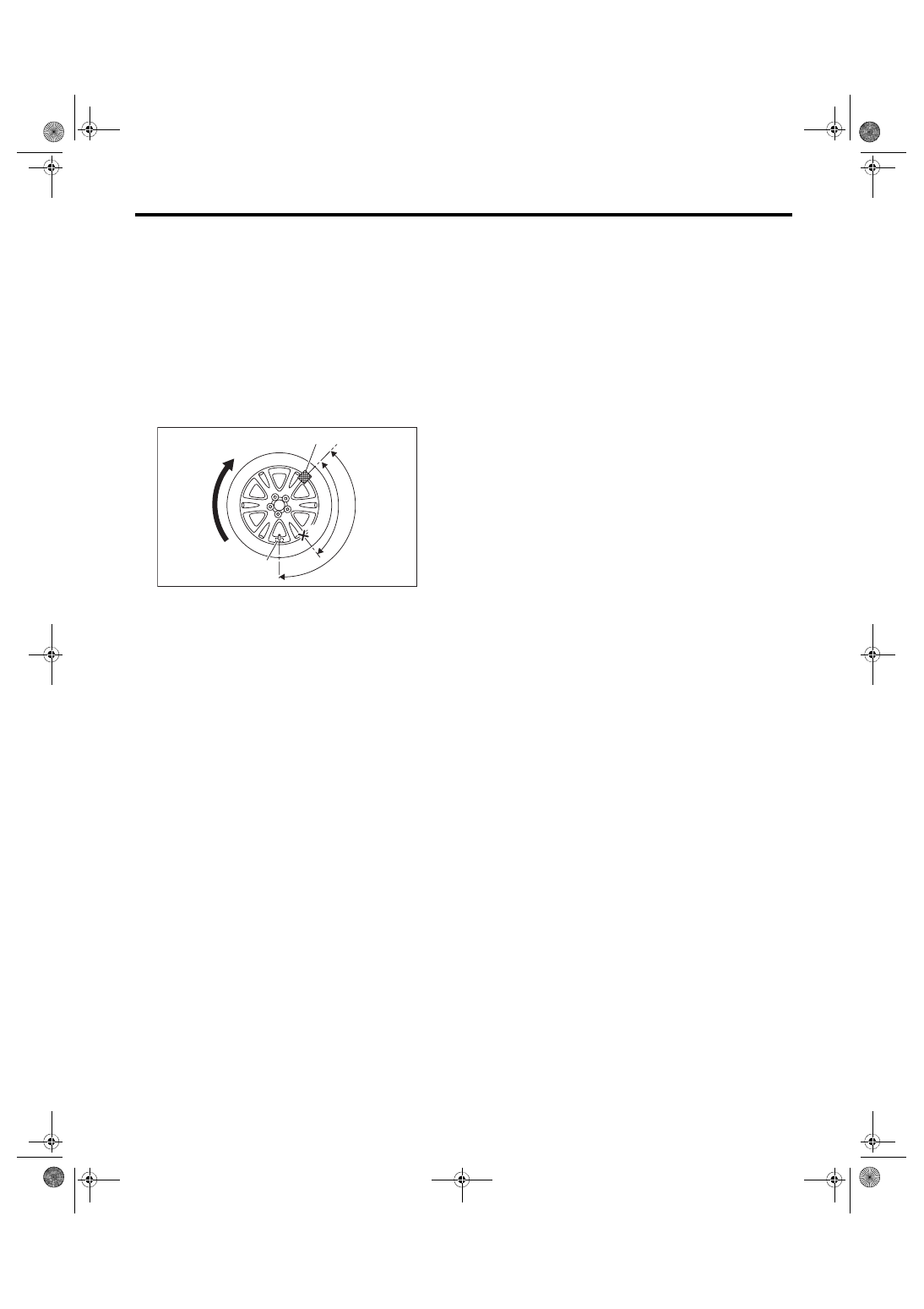
3) Loosen the screw to remove the transmitter from
the valve stem.
NOTE:
Replace the valve and screw with a new part when
reusing transmitter.
4) Remove the valve from the wheel.
2. TPMS & KEYLESS ENTRY CONTROL
MODULE
NOTE:
TPMS control module is integrated into keyless en-
try control module.
1) Disconnect the ground cable from battery.
2) Remove the left rear quarter trim. (5 door model)
<Ref. to EI-60, REMOVAL, Rear Quarter Trim.>
3) Remove the rear shelf trim. (4 door model) <Ref.
to EI-62, REMOVAL, Rear Shelf Trim.>
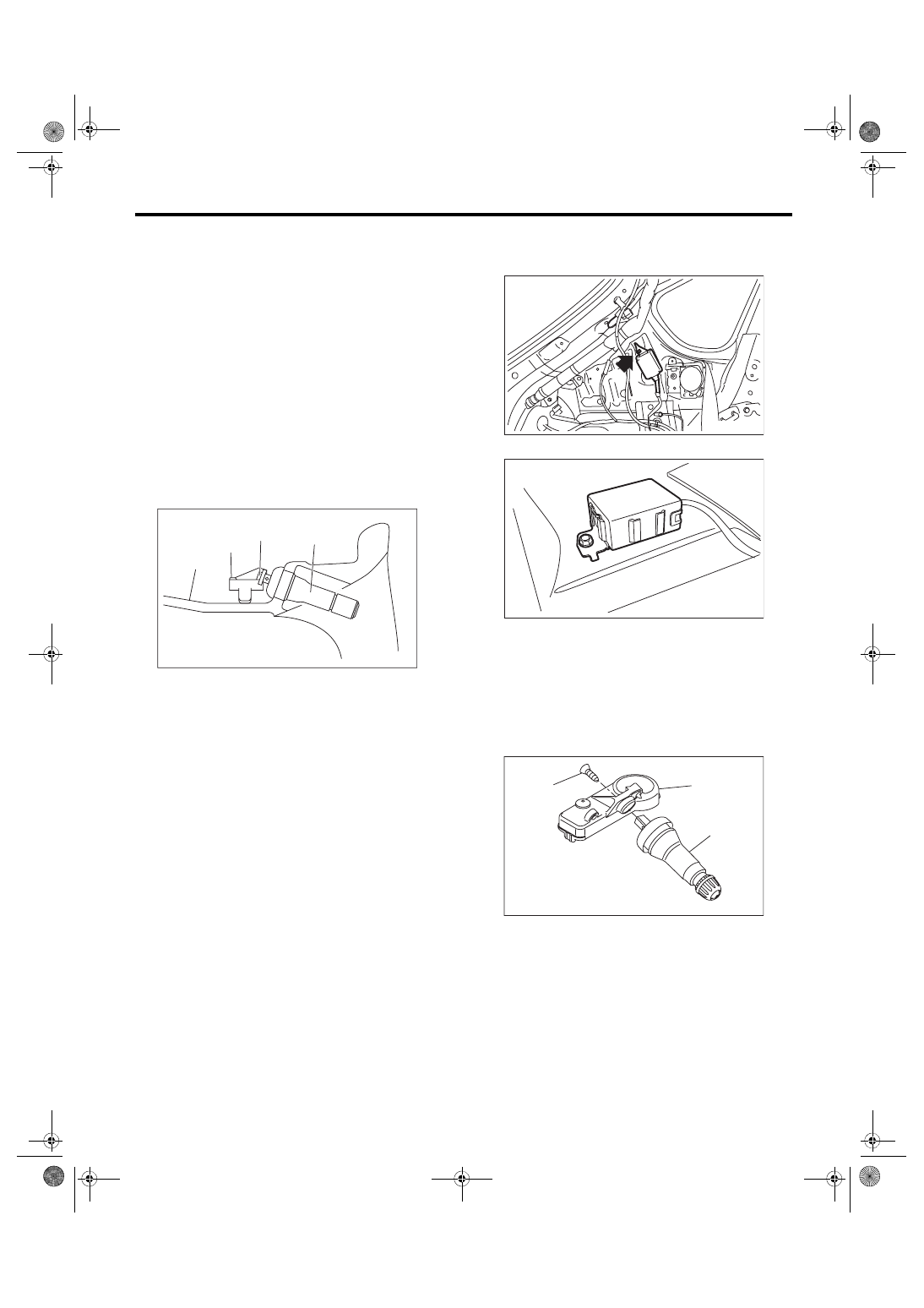
4) Disconnect the harness connector.
5) Remove the bolt and then remove the TPMS &
keyless entry control module.
• 5 door model
• 4 door model
B: INSTALLATION
1. TRANSMITTER (SNAP IN TYPE)
CAUTION:
Use the new transmitter assembly or replace
the new valve and screw, when installing.
1) Replace the valve and screw with a new part
when reusing transmitter.
Tightening torque:
1.4 N·m (0.14 kgf-m, 1 ft-lb)
(1) Wheel
(2) Transmitter
(3) Screw
(4) Valve
WT-00125
(1)
(2)
(4)
(3)
(1) Screw
(2) Transmitter
(3) Valve
SL-00747
SL-00800
WT-00167
(2)
(3)
(1)
WT-9
Tire Pressure Monitoring System
WHEEL AND TIRE SYSTEM
2) Install the transmitter to the wheel by aligning it
with valve hole.
NOTE:
When using the jig that pulls the valve cap by hook-
ing its neck part, use another short-type cap.
3) Install the tires to wheels.
CAUTION:
• Use a tire changer when installing tire to
wheel.
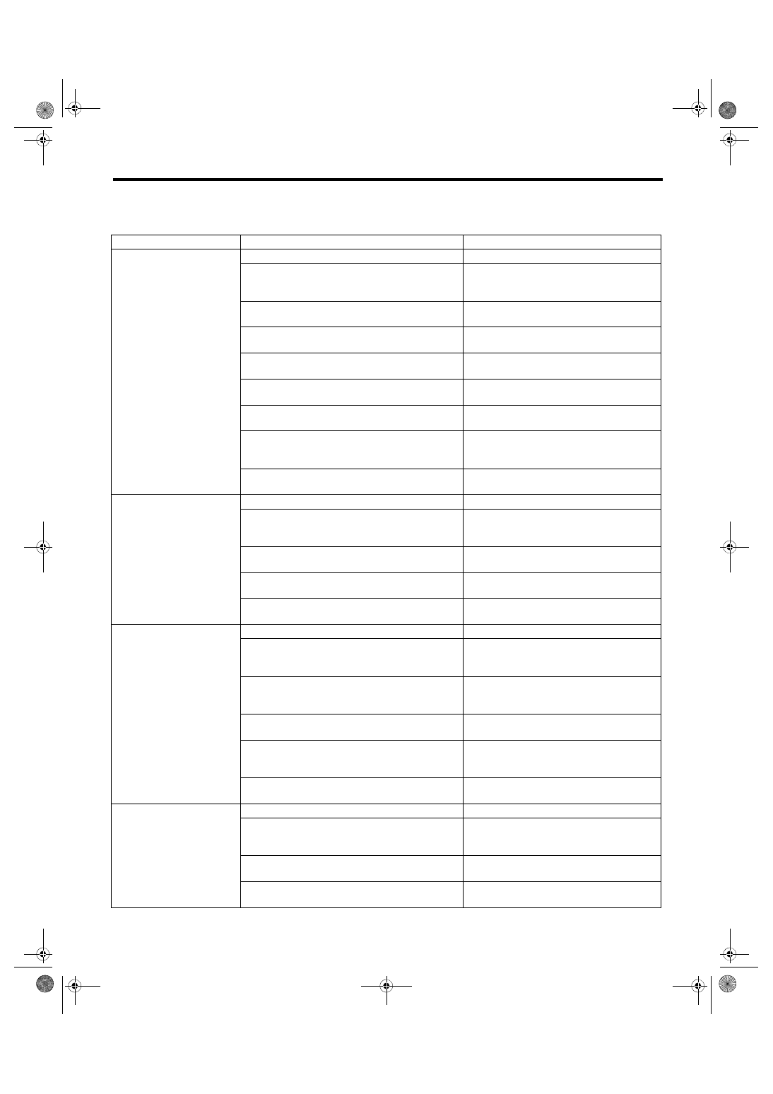
• To prevent damaging the transmitter, set the
tire changer boom in the position as shown in
the figure.
4) Install the wheels to vehicle. <Ref. to WT-4, IN-
5) Register the transmitter ID to the TPMS & key-
less entry control module. <Ref. to TPM(diag)-9,
REGISTER TRANSMITTER ID, OPERATION,
2. TPMS & KEYLESS ENTRY CONTROL
MODULE
Install each part in the reverse order of removal.
Tightening torque:
13 N·m (1.33 kgf-m, 9.6 ft-lb)
C: ADJUSTMENT
Re-register the transmitter ID when transmitter has
been replaced. <Ref. to TPM(diag)-9, REGISTER
TRANSMITTER ID, OPERATION, Subaru Select
Re-register the keyless transmitter when TPMS &
keyless entry control module has been replaced.
<Ref. to SL-49, REGISTRATION OF KEYLESS
TRANSMITTER WITH SUBARU SELECT MONI-
TOR, REPLACEMENT, Transmitter.>
(1) Transmitter
(2) Direction of turn table rotation
(3) 135°
(4) Tire changer boom
(5) 90°
(6) Starting point for fitting the bead to the rim
(1)
(6)
(5)
(3)
(4)
(2)
WT-00130
WT-10
General Diagnostic Table
WHEEL AND TIRE SYSTEM
5. General Diagnostic Table
A: INSPECTION
Symptoms
Possible cause
Corrective action
Wheel is out of balance.
Improperly inflated tire.
Adjust the tire pressure.
Uneven wear
Check the tire referring to Abnormal tire wear
in this table, carry out the procedure and
replace the tire.
Front wheel alignment
Check the front wheel alignment. <Ref. to
FS-8, INSPECTION, Wheel Alignment.>
Rear wheel alignment
Check the rear wheel alignment. <Ref. to RS-
8, INSPECTION, Wheel Alignment.>
Front strut
Check the front strut. <Ref. to FS-26,
INSPECTION, Front Strut.>
Rear shock absorber
Check the rear shock absorber. <Ref. to RS-
14, INSPECTION, Rear Shock Absorber.>
Front axle
Check the front axle. <Ref. to DS-17,
INSPECTION, Front Axle.>
Front hub unit bearing
Check the front hub unit bearing. <Ref. to
DS-19, INSPECTION, Front Hub Unit Bear-
ing.>
Rear hub unit bearing
Check the rear hub unit bearing. <Ref. to DS-
26, INSPECTION, Rear Hub Unit Bearing.>
Vehicle is abnormally out of
balance.
Improperly inflated tire.
Adjust the tire pressure.
Uneven wear
Check the tire referring to Abnormal tire wear
in this table, carry out the procedure and
replace the tire.
Front stabilizer
Inspect the front stabilizer. <Ref. to FS-17,
INSPECTION, Front Stabilizer.>
Front wheel alignment
Check the front wheel alignment. <Ref. to
FS-8, INSPECTION, Wheel Alignment.>
Rear wheel alignment
Check the rear wheel alignment. <Ref. to RS-
8, INSPECTION, Wheel Alignment.>
Abnormal wheel vibration
Improperly inflated tire.
Adjust the tire pressure.
Uneven wear
Check the tire referring to Abnormal tire wear
in this table, carry out the procedure and
replace the tire.
Improper wheel balancing
Check the wheel balance. <Ref. to WT-6,
WHEEL BALANCING, INSPECTION, Tire
and Wheel.>
Front axle
Check the front axle. <Ref. to DS-17,
INSPECTION, Front Axle.>
Front hub unit bearing
Check the front hub unit bearing. <Ref. to
DS-19, INSPECTION, Front Hub Unit Bear-
ing.>
Rear hub unit bearing
Check the rear hub unit bearing. <Ref. to DS-
26, INSPECTION, Rear Hub Unit Bearing.>
Abnormal tire wear
Improperly inflated tire.
Adjust the tire pressure.
Improper wheel balancing
Check the wheel balance. <Ref. to WT-6,
WHEEL BALANCING, INSPECTION, Tire
and Wheel.>
Front wheel alignment
Check the front wheel alignment. <Ref. to
FS-8, INSPECTION, Wheel Alignment.>
Rear wheel alignment
Check the rear wheel alignment. <Ref. to RS-
8, INSPECTION, Wheel Alignment.>
Нет комментариевНе стесняйтесь поделиться с нами вашим ценным мнением.
Текст