Subaru Impreza 3 / Impreza WRX / Impreza WRX STI. Service manual — part 121
FU(w/o STI)-11
General Description
FUEL INJECTION (FUEL SYSTEMS)
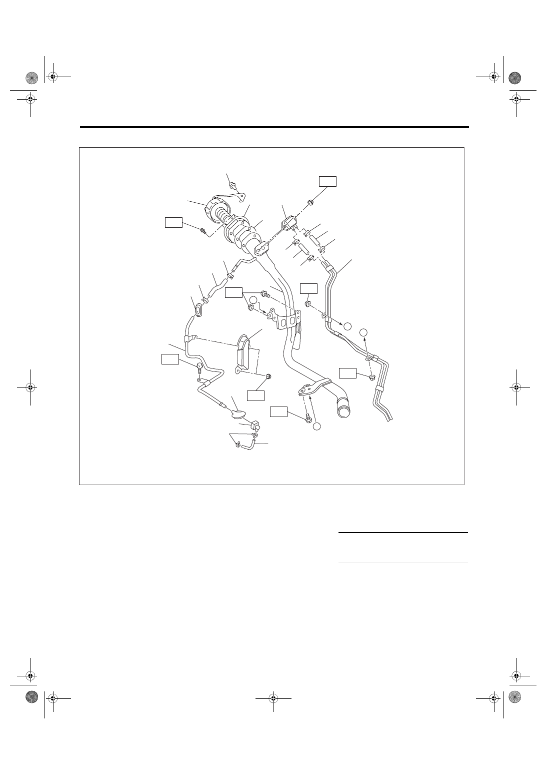
6. FUEL FILLER PIPE
(1)
Fuel filler pipe
(8)
Clip
(15) Grommet
(2)
Evaporation pipe A
(9)
Evaporation hose A
(16) Quick connector
(3)
Fuel filler cap
(10) Clip
(17) Evaporation hose C
(4)
Clip
(11) Evaporation hose B
(5)
Filler ring
(12) Grommet
Tightening torque: N·m (kgf-m, ft-lb)
(6)
Filler pipe gasket
(13) Evaporation pipe B
T1: 4.4 (0.4, 3.2)
(7)
Shut valve
(14) Evaporation pipe protector
T2: 7.5 (0.8, 5.5)
FU-06742
(5)
(6)
(7)
(3)
(1)
(8)
(8)
(9)
(9)
T2
A
B
T2
T1
T1
(4)
(10)
(11)
(13)
(14)
(15)
(16)
(17)
(10)
T2
T2
(10)
(12)
(2)
(8)
(8)
B
A
T2
T2
FU(w/o STI)-12
General Description
FUEL INJECTION (FUEL SYSTEMS)
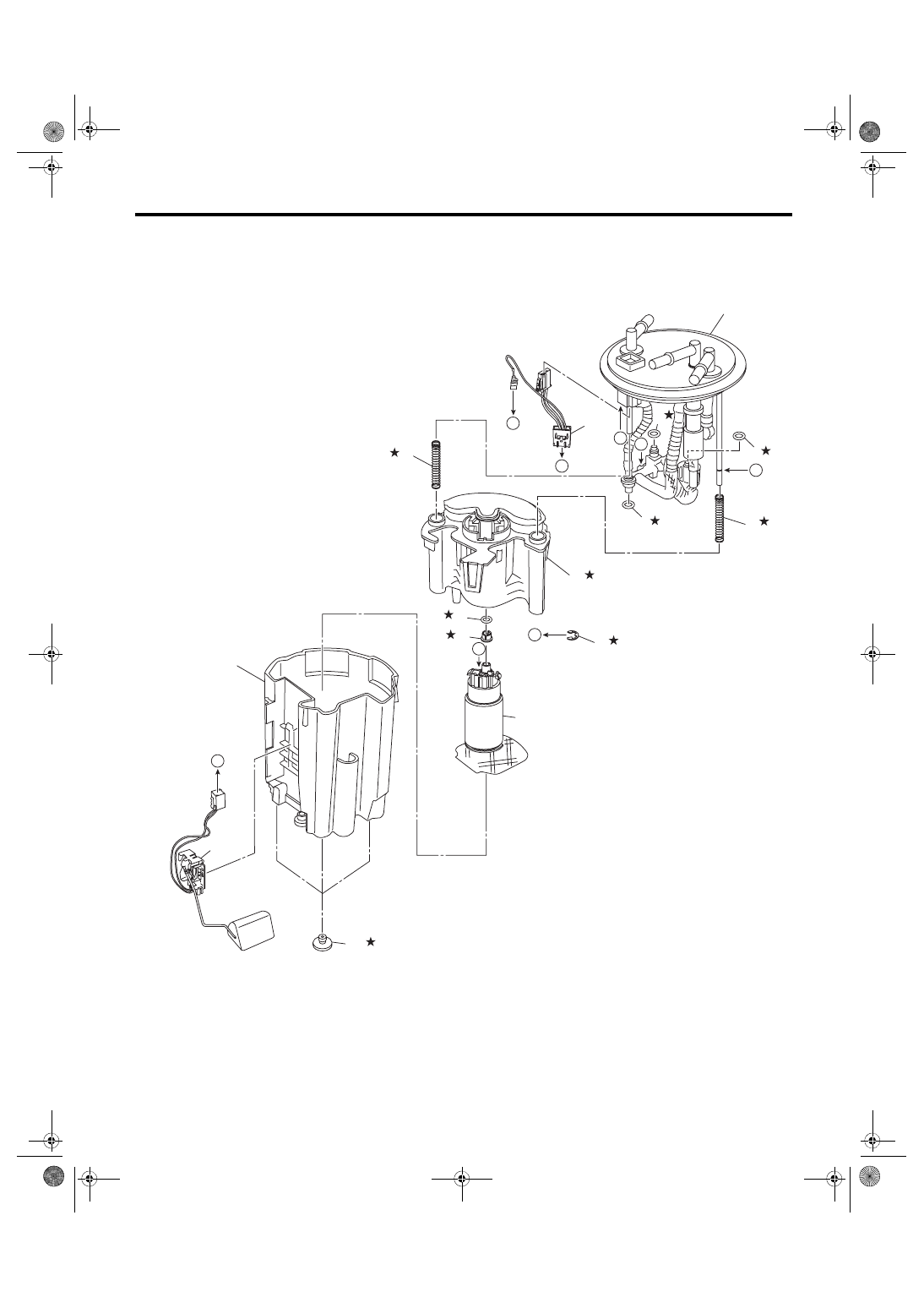
7. FUEL PUMP
(1)
Sub tank bracket ASSY
(5)
Spring
(9)
Pump ASSY
(2)
O-ring
(6)
Fuel filter
(10) Sub tank
(3)
O-ring
(7)
Clip
(11) Cushion
(4)
Fuel pump harness
(8)
Spacer
(12) Fuel level sensor
(2)
(1)
(2)
(3)
(4)
(5)
(5)
(6)
(2)
(8)
(9)
(10)
(11)
(7)
FU-05444
(12)
C
C
A
B
B
A
D
D
FU(w/o STI)-13
General Description
FUEL INJECTION (FUEL SYSTEMS)
C: CAUTION
• Prior to starting work, pay special attention to the following:
1. Always wear work clothes, a work cap, and protective shoes. Additionally, wear a helmet, protective
goggles, etc. if necessary.
2. Protect the vehicle using a seat cover, fender cover, etc.
3. Prepare the service tools, clean cloth, containers to catch grease and oil, etc.
• Place “NO OPEN FLAMES” signs near the working area.
• Prepare a container and cloth to prevent scattering of fuels when performing work where fuels can be
spilled. If the oil spills, wipe it off immediately to prevent from penetrating into floor or flowing out for environ-
mental protection.
• Vehicle components are extremely hot immediately after driving. Be wary of receiving burns from heated
parts.
• When performing a repair, identify the cause of trouble and avoid unnecessary removal, disassembly and
replacement.
• Before disconnecting connectors of sensors or units, be sure to disconnect the ground cable from battery.
• Always use the jack-up point when the shop jacks or rigid racks are used to support the vehicle.
• Remove contamination including dirt and corrosion before removal, installation, disassembly or assembly.
• Keep the removed parts in order and protect them from dust and dirt.
• All removed parts, if to be reused, should be reinstalled in the original positions with attention to the correct
directions, etc.
• Bolts, nuts and washers should be replaced with new parts as required.
• Follow all government and local regulations concerning disposal of refuse when disposing fuel.
ing angle sensor. <Ref. to VDC-13, ADJUSTMENT, VDC Control Module and Hydraulic Control Unit (VDC-
D: PREPARATION TOOL
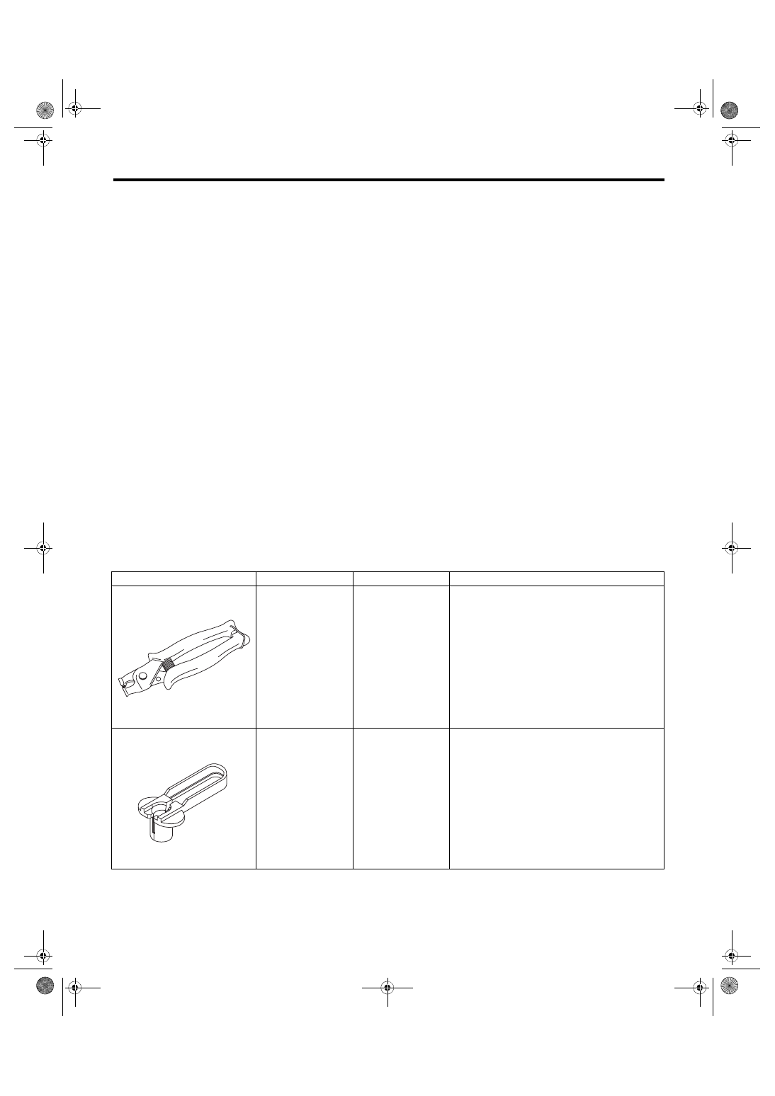
1. SPECIAL TOOL
ILLUSTRATION
TOOL NUMBER
DESCRIPTION
REMARKS
18353AA000
CLAMP PLIERS
• Used for removing and installing the PCV
hose.
• This tool is made by the French company
CAILLAU. (code) 54.0.000.205
To make it easier to obtain, it has been provided
with a tool number.
18371AA000
CONNECTOR
REMOVER
Used for disconnecting the quick connector on
the fuel return hose side of the engine compart-
ment (intake manifold).
ST18353AA000
ST18371AA000
FU(w/o STI)-14
General Description
FUEL INJECTION (FUEL SYSTEMS)
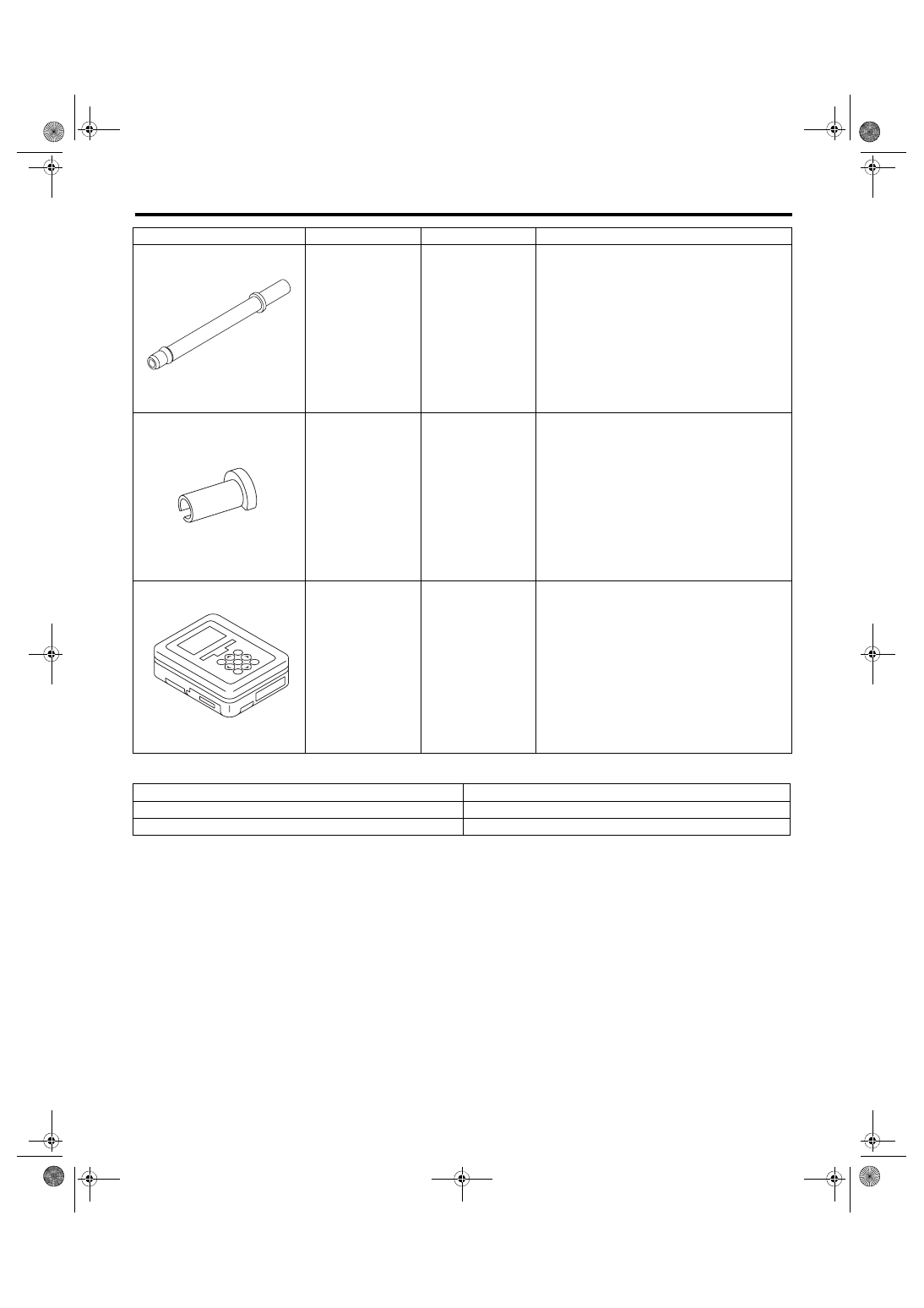
2. GENERAL TOOL
18471AA000
FUEL PIPE
ADAPTER
Used for draining fuel.
42099AE000
QUICK CONNEC-
TOR RELEASE
Used for removing the quick connector.
1B022XU0
SUBARU SELECT
MONITOR III KIT
Used for draining fuel and each inspection.
TOOL NAME
REMARKS
Circuit tester
Used for measuring resistance and voltage.
Oscilloscope
Used for inspecting the waveform of each sensor.
ILLUSTRATION
TOOL NUMBER
DESCRIPTION
REMARKS
ST18471AA000
ST42099AE000
ST1B022XU0
Нет комментариевНе стесняйтесь поделиться с нами вашим ценным мнением.
Текст