Subaru Impreza 3 / Impreza WRX / Impreza WRX STI. Service manual — part 256
EN(H4DOTC)(diag)-248
Diagnostic Procedure with Diagnostic Trouble Code (DTC)
ENGINE (DIAGNOSTICS)
Step
Check
Yes
No
1
CHECK HARNESS BETWEEN ECM AND
SECONDARY AIR COMBINATION VALVE
RELAY 2 CONNECTOR.
1) Turn the ignition switch to OFF.
2) Disconnect the connector from ECM.
3) Remove the secondary air combination
valve relay 2.
4) Measure the voltage between ECM connec-
tor and chassis ground.
Connector & terminal
(B135) No. 20 (+) — Chassis ground (–):
Is the voltage 10 V or more?
Repair the short
circuit to power in
harness between
ECM connector
and secondary air
combination valve
relay 2 connector.
Repair the poor
contact of ECM
connector.
EN(H4DOTC)(diag)-249
Diagnostic Procedure with Diagnostic Trouble Code (DTC)
ENGINE (DIAGNOSTICS)
CF:DTC P0420 CATALYST SYSTEM EFFICIENCY BELOW THRESHOLD (BANK 1)
DTC DETECTING CONDITION:
• Detected when 2 consecutive driving cycles with fault occur.
• GENERAL DESCRIPTION <Ref. to GD(H4DOTC)-150, DTC P0420 CATALYST SYSTEM EFFICIENCY
BELOW THRESHOLD (BANK 1), Diagnostic Trouble Code (DTC) Detecting Criteria.>
TROUBLE SYMPTOM:
• Engine stalls.
• Idle mixture is out of specifications.
CAUTION:
After servicing or replacing faulty parts, perform Clear Memory Mode <Ref. to EN(H4DOTC)(diag)-63,
OPERATION, Clear Memory Mode.>, and Inspection Mode <Ref. to EN(H4DOTC)(diag)-49, PROCE-
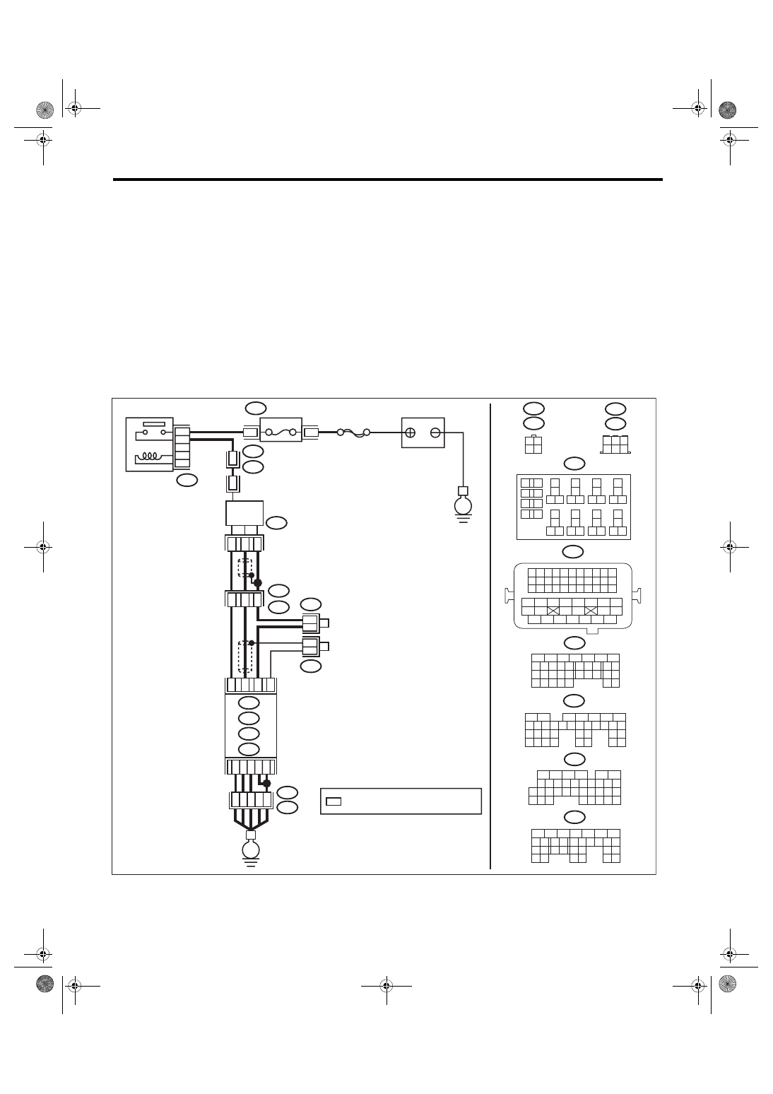
WIRING DIAGRAM:
• Models without SI-DRIVE <Ref. to WI-32, WITHOUT SI-DRIVE, WIRING DIAGRAM, Engine Electrical
ECM
6
4 5
3
2
1
*
2
1
B220
15A
9
10
11
12
B220
*
*
1 2
3 4
D1
36
A4
40
34
35
B21
E2
D3
A6
A3
B220
13
14
15 16
17
27
24
25
26
20
21
22
23
29
30
31
28
32 35
33
34
37
38
39
36
40
8
9
10
11 12
1
2
5
3
4
7
6
19
18
B134
5
6
7
8
2
1
9
4
3
10
24
22 23
25
11 12 13 14 15
26 27
28
16 17
18 19 20 21
33 34
29
32
30 31
A:
D: B137
C: B136
B: B135
A:
T6
B134
C9
B30
C20
B6
*
*
B21
1 2 3 4
12 13 14 15
5 6 7 8
16 17 18 19
9 10 11
20 21 22
23 24 25 26 27 28 29 30 31 32 33
35
34
37
36
39
38
41
40
43
42
44 45
47
46
49
48
51
50
53
52
54
4
1
3
4
1
3
B19
T5
22
T5
B19
5
6
7
8
2
1
9
4
3
10
22 23
11 12 13 14 15
24 25
26
16 17
18 19 20 21
27
28 29
30 31
B135
B:
5
6
7
8
2
1
9
4
3
10
24
22 23
25
11 12 13 14 15
26 27
28
16 17 18 19
20 21
29 30 31
32 33
34 35
B136
C:
5
6
7 8
2
1
9
4
3
10
24
22 23
25
11 12 13 14 15
26 27
28
16
17 18 19 20 21
33 34
29
32
30
31
35
D: B137
B19
T6
B83
B138
B138
B83
EN-08722
E
E
SBF-5
BATTERY
: TERMINAL No. OPTIONAL ARRANGEMENT
REAR
OXYGEN SENSOR
A/F, OXYGEN SENSOR
RELAY
FUSE
(RELAY BLOCK)
EN(H4DOTC)(diag)-250
Diagnostic Procedure with Diagnostic Trouble Code (DTC)
ENGINE (DIAGNOSTICS)
• Models with SI-DRIVE <Ref. to WI-48, WITH SI-DRIVE, WIRING DIAGRAM, Engine Electrical System.>
Step
Check
Yes
No
1
CHECK EXHAUST SYSTEM.
Check for gas leaks or air suction caused by
loose or dislocated nuts and bolts, and open
hole at exhaust pipes.
NOTE:
Check the following positions.
• Between cylinder head and front exhaust
pipe
• Between front exhaust pipe and front catalytic
converter
• Between front catalytic converter and rear
catalytic converter
• Loose or improperly attached front oxygen
(A/F) sensor or rear oxygen sensor
Is there any fault in exhaust
system?
Repair or replace
the exhaust sys-
tem. <Ref. to
EX(STI)-2, Gen-
eral Description.>
ECM
6
4 5
3
2
1
*
2
1
B220
15A
9
10
11
12
B220
*
*
1 2
3 4
D1
36
D3 A4
40
34
35
B21
E2
A6
A3
B220
13
14
15 16
17
27
24
25
26
20
21
22
23
29
30
31
28
32 35
33
34
37
38
39
36
40
8
9
10
11 12
1
2
5
3
4
7
6
19
18
B134
5
6
7
8
2
1
9
4
3
10
24
22 23
25
11 12 13 14 15
26 27
28
16 17
18 19 20 21
33 34
29
32
30 31
A:
D: B137
C: B136
B: B135
A:
T6
B134
C9
B30
C20
B6
*
*
B21
1 2 3 4
12 13 14 15
5 6 7 8
16 17 18 19
9 10 11
20 21 22
23 24 25 26 27 28 29 30 31 32 33
35
34
37
36
39
38
41
40
43
42
44 45
47
46
49
48
51
50
53
52
54
4
1
3
4
1
3
B19
T5
22
T5
B19
5
6
7
8
2
1
9
4
3
10
22 23
11 12 13 14 15
24 25
26
16 17
18 19 20 21
27
28 29
30 31
B135
B:
5
6
7
8
2
1
9
4
3
10
24
22 23
25
11 12 13 14 15
26 27
28
16 17 18 19
20 21
29 30 31
32 33
34 35
B136
C:
5
6
7 8
2
1
9
4
3
10
24
22 23
25
11 12 13 14 15
26 27
28
16
17 18 19 20 21
33 34
29
32
30
31
35
D: B137
B19
T6
B83
B138
B138
B83
EN-08723
SBF-5
E
E
BATTERY
: TERMINAL No. OPTIONAL ARRANGEMENT
REAR
OXYGEN SENSOR
A/F, OXYGEN SENSOR
RELAY
FUSE
(RELAY BLOCK)
EN(H4DOTC)(diag)-251
Diagnostic Procedure with Diagnostic Trouble Code (DTC)
ENGINE (DIAGNOSTICS)
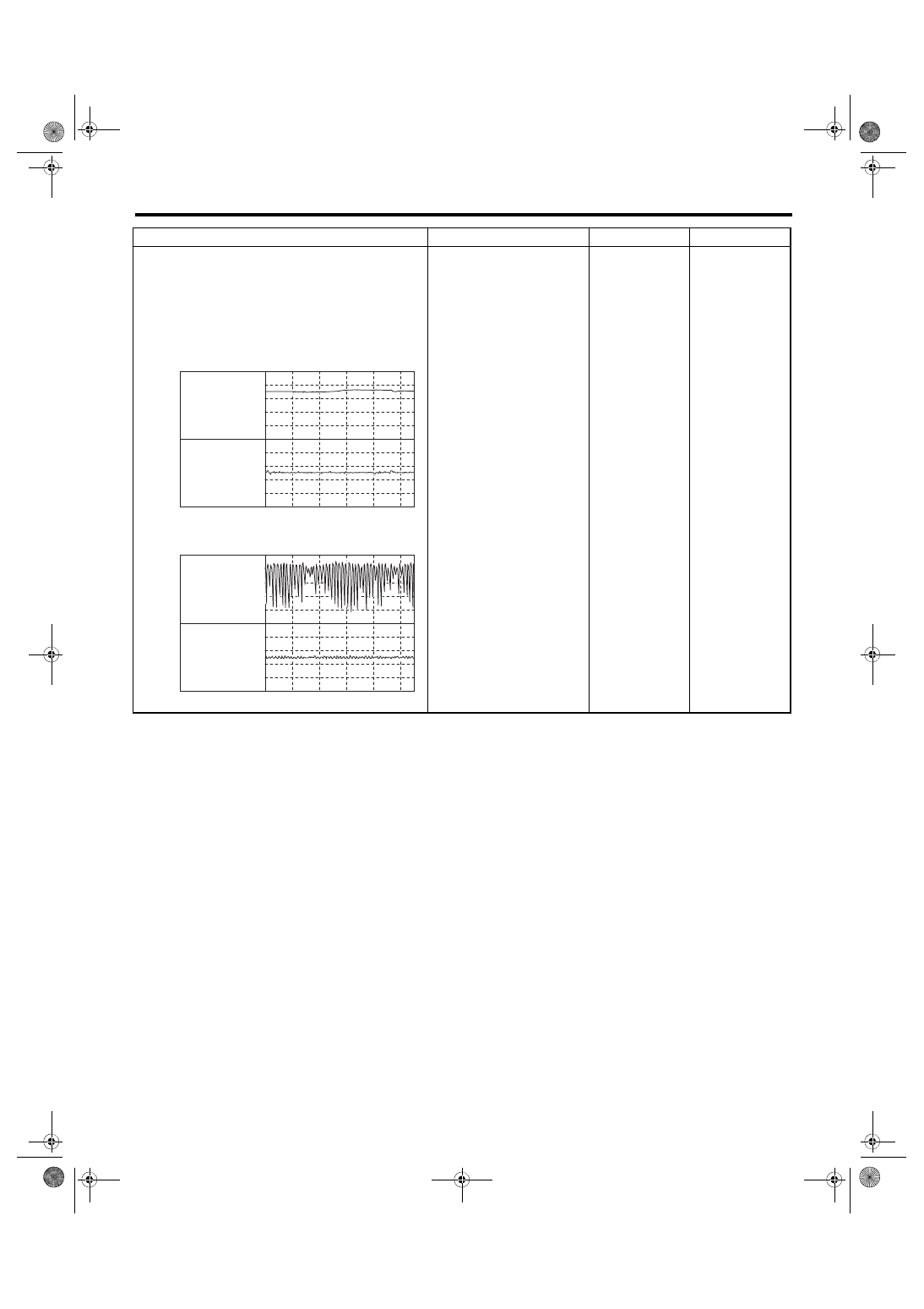
2
CHECK WAVEFORM DATA ON THE SUBA-
RU SELECT MONITOR (WHILE DRIVING).
1) Drive at a constant speed between 80 —
112 km/h (50 — 70 MPH).
2) After 5 minutes have elapsed in the condi-
tion of step 1), use the Subaru Select Monitor
while still driving to read the waveform data.
• At normal condition
• At abnormal condition (numerous inversion)
Is a normal waveform dis-
played?
Even if DTC is
detected, the cir-
cuit has returned to
a normal condition
at this time. Repro-
duce the failure,
and then perform
the diagnosis
again.
NOTE:
In this case, tem-
porary poor con-
tact of connector,
temporary open or
short circuit of har-
ness may be the
cause.
Step
Check
Yes
No
EN-06666
1
0
1.5
0.5
10 sec/div
REAR OXYGEN
SENSOR VOLTAGE
(V)
A/F SENSOR
OUTPUT LAMBDA 1
EN-06667
1
0
1.5
0.5
10 sec/div
REAR OXYGEN
SENSOR VOLTAGE
(V)
A/F SENSOR
OUTPUT LAMBDA 1
Нет комментариевНе стесняйтесь поделиться с нами вашим ценным мнением.
Текст