Subaru Impreza 3 / Impreza WRX / Impreza WRX STI. Service manual — part 596
AC-43
Pressure Switch (Triple Pressure Switch)
HVAC SYSTEM (HEATER, VENTILATOR AND A/C)
21.Pressure Switch (Triple Pressure Switch)
A: INSPECTION
1) Connect the manifold gauge to the service valve on the high-pressure side.
2) Disconnect the pressure switch connector.
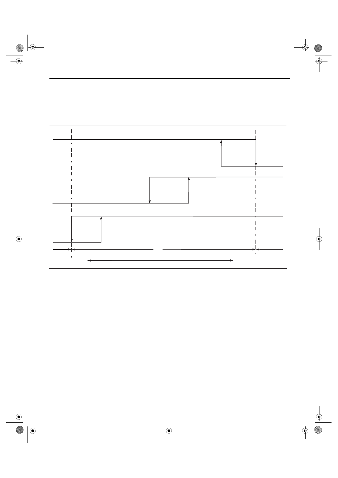
3) Start the air conditioner, and check the operating pressure of switch by turning the compressor (magnet
clutch) to ON/OFF. Operation of each switch is as follows.
NOTE:
• High pressure switch turns the compressor (magnet clutch) to OFF when the refrigerant pressure be-
comes extremely high to prevent the evaporator, air conditioner piping and expansion valve from getting
damaged or frozen, etc.
• Middle pressure switch effectively controls the radiator fan output by judging high load/low load in normal
range.
• The low pressure switch detects a refrigerant shortage and deactivates the compressor (magnet clutch) if
the refrigerant pressure is abnormally low. (Because any further compressor operation in such a state may
lead to compressor seizure)
(1)
High pressure switch
(6)
1,770±100 kPa
(18.05±1.02 kg/cm
2
, 256.65±14.5
psi)
(11) OFF
(2)
Middle pressure switch
(7)
1,470±120 kPa
(14.99±1.22 kg/cm
2
, 213.15±17.4
psi)
(12) Operative range of compressor
(3)
Low pressure switch
(8)
225±30 kPa
(2.30±0.31 kg/cm
2
, 32.6±4.3 psi)
(13) Inoperative range of compressor
(4)
2,350±200 kPa
(24.00±2.04 kg/cm
2
, 340.7±29.0
psi)
(9)
196±25 kPa
(2.0±0.25 kg/cm
2
, 28.4±3.6 psi)
(14) Low pressure
(5)
2,940±200 kPa
(29.98±2.04 kg/cm
2
, 426.3±29.0
psi)
(10) ON
(15) High pressure
AC-02346
(1)
(9)
(2)
(3)
(8)
(4)
(5)
(6)
(7)
(11)
(10)
(10)
(11)
(11)
(10)
(12)
(13)
(13)
(14)
(15)
AC-44
Ambient Sensor (Auto A/C Model)
HVAC SYSTEM (HEATER, VENTILATOR AND A/C)
22.Ambient Sensor (Auto A/C Model)
A: REMOVAL
1) Disconnect the ground cable from battery.
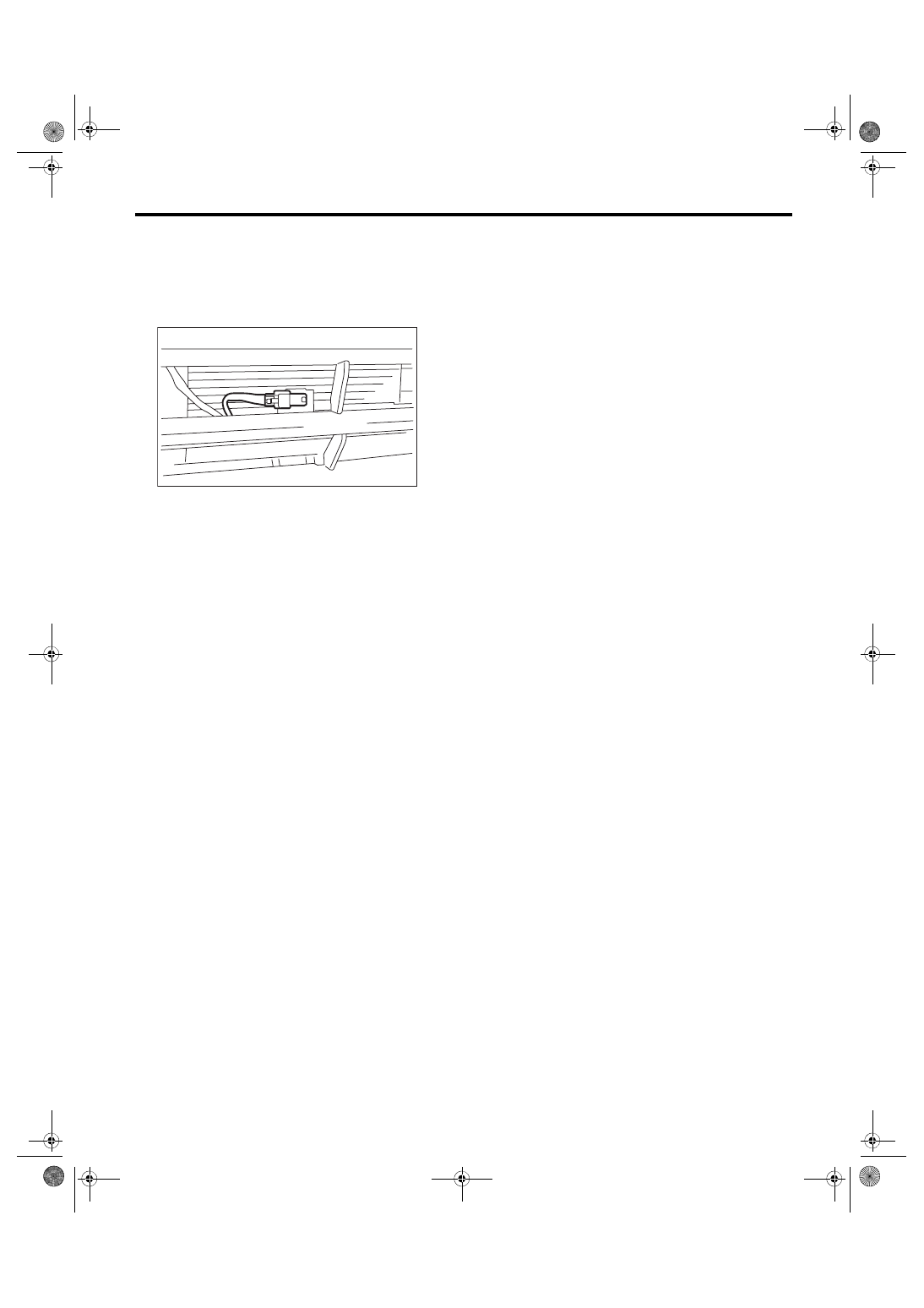
2) Disconnect the ambient sensor connector.
3) Remove the ambient sensor from the radiator lower panel.
B: INSTALLATION
Install each part in the reverse order of removal.
AC-03417
AC-45
Ambient Sensor (Auto A/C Model)
HVAC SYSTEM (HEATER, VENTILATOR AND A/C)
C: INSPECTION
Preparation tool: Circuit tester
1) Visually check the ambient sensor for dirt or damage, and clean or replace as necessary.
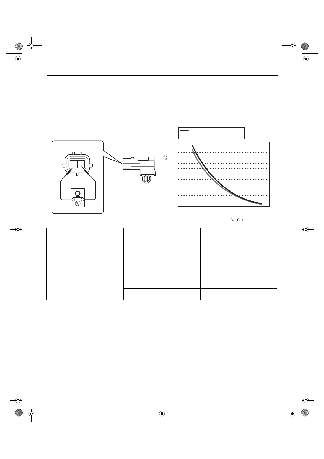
2) Check the resistance between ambient sensor terminals.
CAUTION:
During inspection, be careful not to touch the sensor end in order to avoid misjudgment due to body
temperature.
3) Replace the ambient sensor if the inspection result is not within the standard value.
Terminal No.
Inspection conditions
Standard
1 — 2
10°C
5.82 — 6.18 kΩ
15°C
4.58 — 4.87 kΩ
20°C
3.64 — 3.86 kΩ
25°C
2.91 — 3.09 kΩ
30°C
2.35 — 2.49 kΩ
35°C
1.9 — 2.02 kΩ
40°C
1.56 — 1.65 kΩ
45°C
1.28 — 1.36 kΩ
50°C
1.06 — 1.12 kΩ
55°C
0.88 — 0.93 kΩ
60°C
0.74 — 0.78 kΩ
(140)
(122)
(104)
(86)
(68)
(50)
60
50
40
30
0
(32)
10
20
2 1
AC-03187
0.50
1.00
1.50
2.00
2.50
3.00
3.50
4.00
4.50
5.00
5.50
6.00
6.50
TEMPERATURE
RESIST
ANCE
VALUE
: STANDARD (MIN TOLERANCE)
: STANDARD (MAX TOLERANCE)
AC-46
Sunload Sensor (Auto A/C Model)
HVAC SYSTEM (HEATER, VENTILATOR AND A/C)
23.Sunload Sensor (Auto A/C
Model)
A: REMOVAL
1) Disconnect the ground cable from battery.
2) Remove the audio. (model with audio) <Ref. to
3) Remove the navigation unit. (model with naviga-
tion) <Ref. to ET-14, PROCEDURE, Navigation
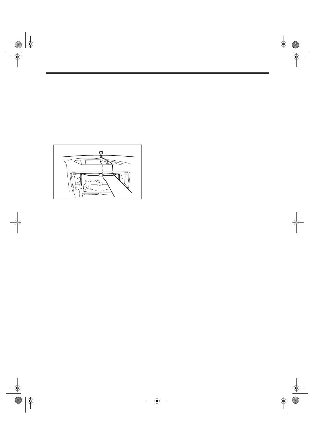
4) Push out the sunload sensor from the back side
of the instrument panel.
5) Disconnect the harness connector and remove
the sunload sensor.
CAUTION:
Be careful not to damage the interior trims
when removing the sensor.
B: INSTALLATION
Install each part in the reverse order of removal.
C: INSPECTION
Refer to “Sunload Sensor” of HVAC SYSTEM (AU-
TO A/C)(DIAGNOSTICS). <Ref. to AC(diag)-35,
SUNLOAD SENSOR, Diagnostic Procedure for
AC-01872
Нет комментариевНе стесняйтесь поделиться с нами вашим ценным мнением.
Текст