Subaru Impreza 3 / Impreza WRX / Impreza WRX STI. Service manual — part 652
AB(diag)-147
Diagnostic Chart with Trouble Code
AIRBAG SYSTEM (DIAGNOSTICS)
BP:DTC E3 FRONT SENSOR BUS RH COMMUNICATION ERROR
NOTE:
Refer to DTC A1 for DTC E3. <Ref. to AB(diag)-145, DTC A1 FRONT SENSOR BUS COMMUNICATION
ERROR, Diagnostic Chart with Trouble Code.>
BQ:DTC E4 FRONT SENSOR BUS RH COMMUNICATION ERROR
NOTE:
Refer to DTC A1 for DTC E4. <Ref. to AB(diag)-145, DTC A1 FRONT SENSOR BUS COMMUNICATION
ERROR, Diagnostic Chart with Trouble Code.>
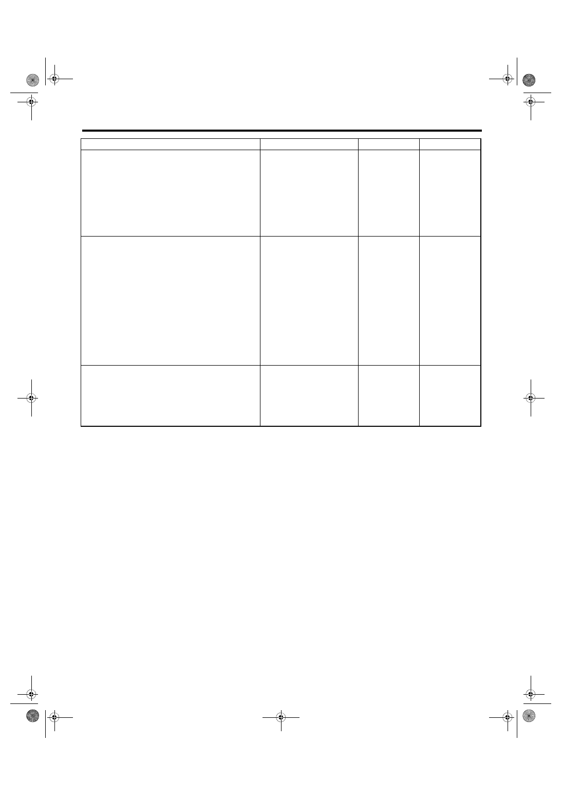
5
CHECK AIRBAG MAIN HARNESS (FRONT
SENSOR BUS RH).
Measure the resistance between connector
(4AG) in the test harness AG and chassis
ground, and the resistance between connector
(4AG) terminals in the test harness AG.
Connector & terminal
(4AG) No. 12 — Chassis ground:
(4AG) No. 14 — Chassis ground:
(4AG) No. 12 — (4AG) No. 14:
Is the resistance 1 MΩ or
more?
Replace the airbag
main harness
along with body
harness.
6
CHECK AIRBAG CONTROL MODULE.
1) Connect all connectors.
2) Clear the memory.
3) Perform the Inspection Mode.
4) Read the DTC.
Is the same DTC displayed?
7
CHECK FOR ANY OTHER DTC ON DISPLAY. Is any other DTC displayed?
Finish the diagno-
sis.
Step
Check
Yes
No
AB(diag)-148
Diagnostic Chart with Trouble Code
AIRBAG SYSTEM (DIAGNOSTICS)
BR:DTC E7 FRONT SENSOR BUS LH COMMUNICATION ERROR
DTC DETECTING CONDITION:
• Open or short circuit in harness of front sensor bus (LH).
• Front sub sensor (LH) is faulty.
• Airbag control module is faulty.
CAUTION:
• Before diagnosing the airbag system, be sure to turn the ignition switch to OFF, disconnect the
ground cable from battery, and wait 60 seconds or more before starting to work.
• When replacing the airbag module, seat belt pretensioner, roll connector, control module and sen-
sor, reconnect each part and check that the warning light operates properly.
• When inspecting the airbag main harness, disconnect the airbag module connectors and seat belt
pretensioner connectors of the driver’s and passenger’s seats for safety reasons.
WIRING DIAGRAM:
Airbag system <Ref. to WI-82, WIRING DIAGRAM, Airbag System.>
Step
Check
Yes
No
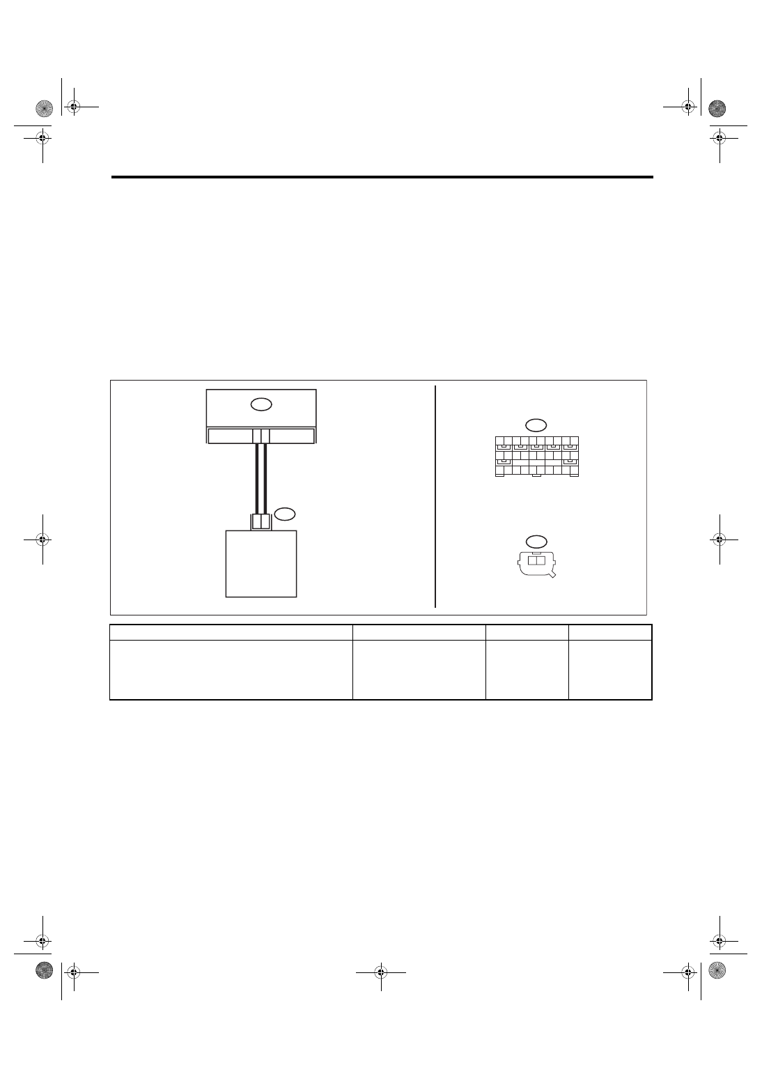
1
CHECK POOR CONTACT OF CONNEC-
TORS.
Check for poor contact of the connectors (AB6,
AB13) between the airbag control module and
the front sub sensor (LH).
Is there poor contact?
Replace the airbag
main harness
along with body
harness.
AB-02466
AB6
1 2 3 4 5 6 7 8 9 10
11 12 13 14 15 16 17 18 19 20
21 22 23 24 25 26 27 28 29 30
1 2
AB13
0
3
8
2
AB13
1
2
AB6
AIRBAG CM
FRONT SUB SENSOR LH
AB(diag)-149
Diagnostic Chart with Trouble Code
AIRBAG SYSTEM (DIAGNOSTICS)
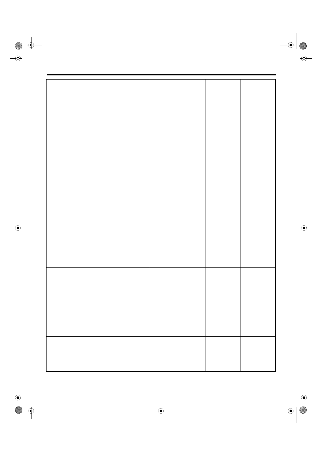
2
CHECK AIRBAG MAIN HARNESS (FRONT
SENSOR BUS LH).
1) Turn the ignition switch to OFF, disconnect
the battery ground cable, and wait for 60 sec-
onds or more.
2) Remove the instrument panel lower cover
and column cover, and disconnect the connec-
tors (AB7) and (AB2).
3) Remove the console front panel and discon-
nect the connector (AB9).
4) Disconnect the connectors (AB6, AB17,
AB18) from airbag control module.
5) Connect the connector (1AH) in the test har-
ness AH to the connectors (AB6, AB17, AB18).
6) Connect the connector (2AH) in the test har-
ness AH and the connector (1AG) in the test
harness AG.
7) Disconnect the connector (AB13) from the
front sub sensor (LH), and then connect the
connector (1H) in the test harness H to connec-
tor (AB13).
8) Measure the resistance between connector
(4AG) in the test harness AG and connector
(3H) in the test harness H.
Connector & terminal
(4AG) No. 7 — (3H) No. 5:
(4AG) No. 9 — (3H) No. 6:
Is the resistance less than 10
Ω?
Replace the airbag
main harness
along with body
harness.
3
CHECK AIRBAG MAIN HARNESS (FRONT
SENSOR BUS LH).
Measure the resistance between connector
(4AG) in the test harness AG and chassis
ground, and the resistance between connector
(4AG) terminals in the test harness AG.
Connector & terminal
(4AG) No. 7 — Chassis ground:
(4AG) No. 9 — Chassis ground:
(4AG) No. 7 — (4AG) No. 9:
Is the resistance 1 MΩ or
more?
Replace the airbag
main harness
along with body
harness.
4
CHECK AIRBAG CONTROL MODULE.
1) Connect all connectors.
2) Clear the memory.
3) Perform the Inspection Mode.
4) Read the DTC.
Is the same DTC displayed?
5
CHECK FOR ANY OTHER DTC ON DISPLAY. Is any other DTC displayed?
Finish the diagno-
sis.
Step
Check
Yes
No
AB(diag)-150
Diagnostic Chart with Trouble Code
AIRBAG SYSTEM (DIAGNOSTICS)
BS:DTC E8 FRONT SENSOR BUS LH COMMUNICATION ERROR
NOTE:
Refer to DTC E7 for DTC E8. <Ref. to AB(diag)-148, DTC E7 FRONT SENSOR BUS LH COMMUNICATION
ERROR, Diagnostic Chart with Trouble Code.>
BT:DTC E9 SIDE SENSOR BUS RH COMMUNICATION ERROR
NOTE:
Refer to DTC EC for details on DTC E9. <Ref. to AB(diag)-151, DTC EC SIDE SENSOR BUS RH COMMU-
NICATION ERROR, Diagnostic Chart with Trouble Code.>
BU:DTC EB SIDE SENSOR BUS RH COMMUNICATION ERROR
NOTE:
Refer to DTC EC for details on DTC EB. <Ref. to AB(diag)-151, DTC EC SIDE SENSOR BUS RH COMMU-
Нет комментариевНе стесняйтесь поделиться с нами вашим ценным мнением.
Текст