Subaru Impreza 3 / Impreza WRX / Impreza WRX STI. Service manual — part 414
5MT-77
Reverse Idler Gear
MANUAL TRANSMISSION AND DIFFERENTIAL
18.Reverse Idler Gear
A: REMOVAL
1) Remove the manual transmission assembly
from the vehicle. <Ref. to 5MT-23, REMOVAL,
Manual Transmission Assembly.>
2) Remove the back-up light switch and the neutral
position switch. <Ref. to 5MT-33, REMOVAL,
3) Remove the transfer case together with the ex-
tension case assembly. <Ref. to 5MT-35, REMOV-
AL, Transfer Case and Extension Case
4) Remove the transmission case. <Ref. to 5MT-
49, REMOVAL, Transmission Case.>
5) Remove the drive pinion shaft assembly. <Ref.
to 5MT-58, REMOVAL, Drive Pinion Shaft Assem-
6) Remove the main shaft assembly for single-
range. <Ref. to 5MT-53, REMOVAL, Main Shaft
7) Remove the front differential assembly. <Ref. to
5MT-69, REMOVAL, Front Differential Assembly.>
8) Remove the shifter forks and rods. <Ref. to 5MT-
79, REMOVAL, Shifter Fork and Rod.>
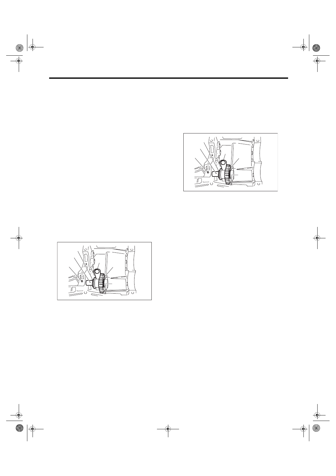
9) Pull out the straight pin, and remove the reverse
idler gear shaft, washer, reverse idler gear and
washer.
10) Remove the reverse shifter lever.
B: INSTALLATION
1) Install the reverse shifter lever, washer, reverse
idler gear, washer and reverse idler gear shaft, and
secure them with the straight pin.
NOTE:
• Be sure to install the reverse idler gear shaft from
rear side.
• Use a new straight pin.
2) Check and adjust clearance between the re-
verse idler gear and the timing case wall surface.
<Ref. to 5MT-77, INSTALLATION, Reverse Idler
Gear.> <Ref. to 5MT-78, ADJUSTMENT, Reverse
3) Install the shifter forks and rods. <Ref. to 5MT-
80, INSTALLATION, Shifter Fork and Rod.>
4) Install the front differential assembly. <Ref. to
5MT-69, INSTALLATION, Front Differential As-
5) Install the main shaft assembly for single-range.
<Ref. to 5MT-53, INSTALLATION, Main Shaft As-
6) Install the drive pinion shaft assembly. <Ref. to
5MT-58, INSTALLATION, Drive Pinion Shaft As-
7) Install the transmission case. <Ref. to 5MT-50,
INSTALLATION, Transmission Case.>
8) Install the transfer case together with the exten-
sion case assembly. <Ref. to 5MT-35, INSTALLA-
TION, Transfer Case and Extension Case
9) Install the back-up light switch and the neutral
position switch. <Ref. to 5MT-33, INSTALLATION,
10) Install the manual transmission assembly to the
vehicle. <Ref. to 5MT-26, INSTALLATION, Manual
(A) Straight pin
(B) Reverse idler gear shaft
(C) Reverse idler gear
(D) Washer
(E) Washer
(F) Reverse shifter lever
MT-01565
(A)
(B)
(C)
(D)
(F)
(E)
(A) Straight pin
(B) Reverse idler gear shaft
(C) Reverse idler gear
(D) Washer
(E) Washer
(F) Reverse shifter lever
MT-01565
(A)
(B)
(C)
(D)
(F)
(E)
5MT-78
Reverse Idler Gear
MANUAL TRANSMISSION AND DIFFERENTIAL
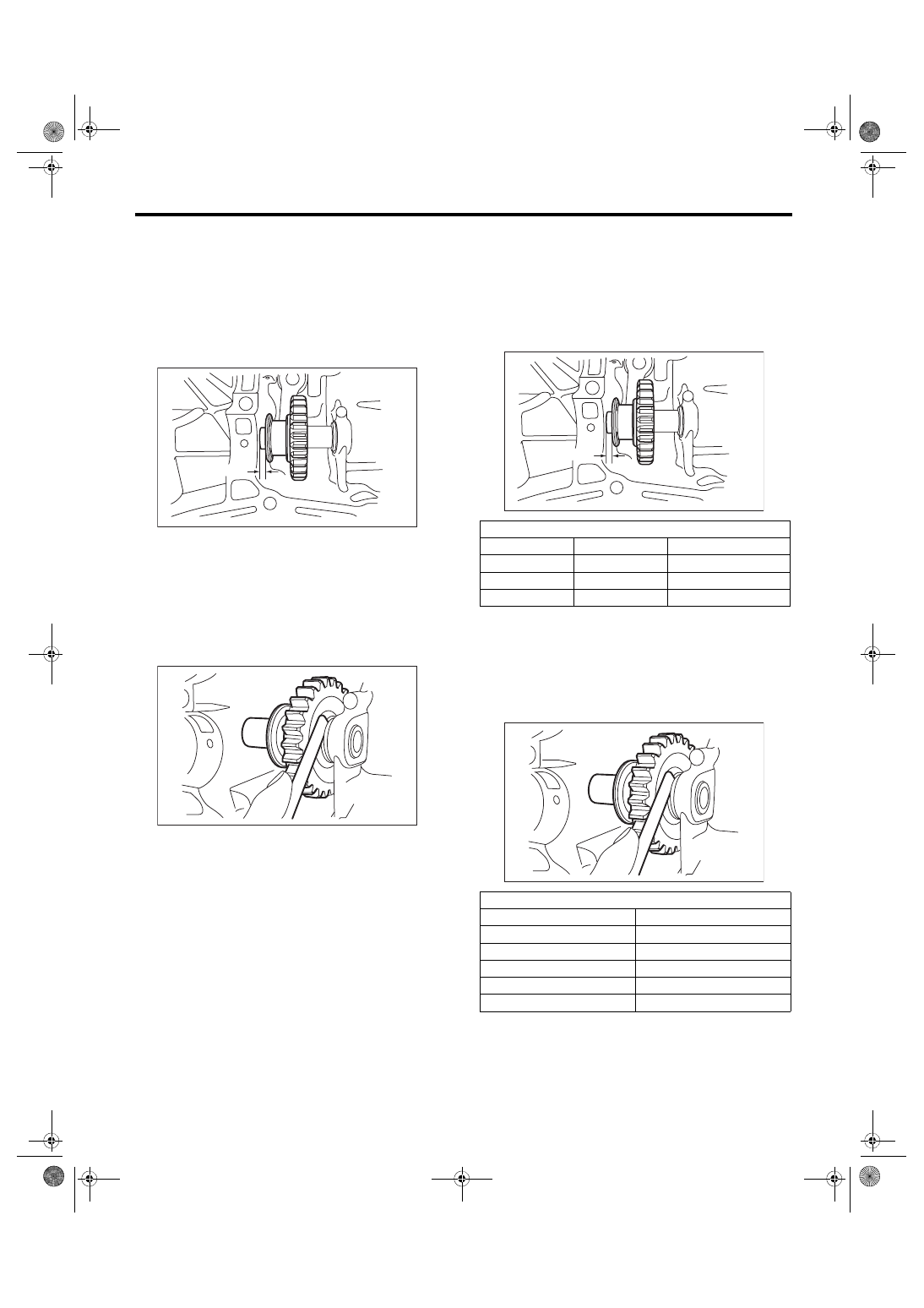
C: INSPECTION
1) Move the reverse shifter rod toward the reverse
side. Check the clearance between the reverse
idler gear and the transmission case wall surface.
If out of specification, select the appropriate re-
verse shifter lever and adjust.
Clearance A:
6.0 — 7.5 mm (0.236 — 0.295 in)
2) After installing a suitable reverse shifter lever,
shift into neutral. Check the clearance between the
reverse idler gear and the transmission case wall
surfaces.
If out of specification, select the appropriate adjust-
ing washer and adjust.
Clearance:
0 — 0.5 mm (0 — 0.020 in)
3) Check the reverse idler gear and shaft for dam-
age. Replace if it is damaged.
D: ADJUSTMENT
1) Select the appropriate reverse shifter lever from
the table below, and adjust until the clearance be-
tween the reverse idler gear and transmission case
wall is within specification.
Clearance A:
6.0 — 7.5 mm (0.236 — 0.295 in)
2) Select the appropriate adjusting washer from the
table below, and adjust until the clearance between
the reverse idler gear and transmission case wall is
within specification.
Clearance:
0 — 0.5 mm (0 — 0.020 in)
MT-00305
A
MT-00306
Reverse shifter lever
Part No.
Mark
Contents
32820AA070
7
Far from case wall
32820AA080
8
Standard
32820AA090
9
Closer to case wall
Adjusting washer
Part No.
Thickness mm (in)
803020151
0.4 (0.016)
803020152
1.1 (0.043)
803020153
1.5 (0.059)
803020154
1.9 (0.075)
803020155
2.3 (0.091)
MT-00305
A
MT-00306
5MT-79
Shifter Fork and Rod
MANUAL TRANSMISSION AND DIFFERENTIAL
19.Shifter Fork and Rod
A: REMOVAL
1) Remove the manual transmission assembly
from the vehicle. <Ref. to 5MT-23, REMOVAL,
Manual Transmission Assembly.>
2) Remove the back-up light switch and the neutral
position switch. <Ref. to 5MT-33, REMOVAL,
3) Remove the transfer case together with the ex-
tension case assembly. <Ref. to 5MT-35, REMOV-
AL, Transfer Case and Extension Case
4) Remove the transmission case. <Ref. to 5MT-
49, REMOVAL, Transmission Case.>
5) Remove the drive pinion shaft assembly. <Ref.
to 5MT-58, REMOVAL, Drive Pinion Shaft Assem-
6) Remove the main shaft assembly for single-
range. <Ref. to 5MT-53, REMOVAL, Main Shaft
7) Remove the front differential assembly. <Ref. to
5MT-69, REMOVAL, Front Differential Assembly.>
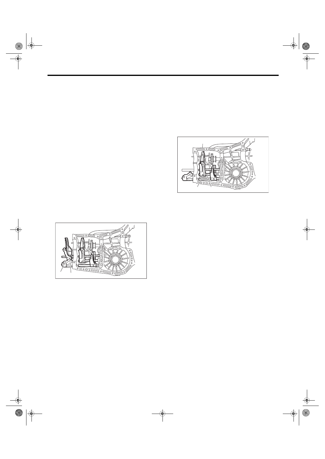
8) Drive out the straight pin by tapping with the ST,
and remove the 5th shifter fork.
ST 398791700
STRAIGHT PIN REMOVER 2
9) Remove the plugs, springs and check balls.
10) Drive out the straight pin by tapping with the
ST, and remove the 3rd – 4th fork rod and shifter
fork.
NOTE:
• When removing the rod, keep other rods in neu-
tral.
• When removing the straight pin, remove it to-
ward the inside of case so that it does not hit
against the case.
ST 398791700
STRAIGHT PIN REMOVER 2
11) Drive out the straight pin by tapping with the
ST, and remove the 1st – 2nd fork rod and shifter
fork.
ST 398791700
STRAIGHT PIN REMOVER 2
12) Remove the snap ring (outer), and pull out the
reverse fork rod from the reverse fork rod arm.
Then take out the ball, spring and interlock plunger
from the reverse fork rod arm.
And then remove the rod.
NOTE:
When pulling out the reverse fork rod arm, be care-
ful not to let the ball pop out of arm.
13) Remove the reverse shifter lever.
(A) Straight pin
(B) 5th shifter fork
MT-00309
( A )
( B )
(A) Straight pin
(B) 3rd-4th fork rod
(C) Shifter fork
MT-00994
(A)
(B)
(C)
5MT-80
Shifter Fork and Rod
MANUAL TRANSMISSION AND DIFFERENTIAL
B: INSTALLATION
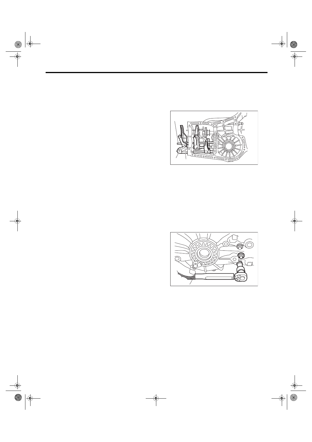
1) Install the spring and ball to the reverse fork rod
arm, and press in the ST.
ST 399411700
ACCENT BALL INSTALLER
2) Install the reverse fork rod through the hole on
the rear of the transmission case. Press out the ST
using the reverse fork rod, and fix with outer snap
ring.
3) Install the interlock plunger to reverse fork rod
arm.
NOTE:
Apply grease to the plunger to prevent it from fall-
ing.
4) Position the ball, spring and gasket in the re-
verse fork rod hole on the left side of transmission
case, and tighten the checking ball plug.
NOTE:
Use a new gasket.
Tightening torque:
20 N·m (2.0 kgf-m, 14.8 ft-lb)
5) Install the 1st-2nd fork rod to the 1st-2nd shifter
fork through the hole on the rear of the transmis-
sion case.
NOTE:
• Set other rods to neutral.
• Check that the positions of interlock plunger is
correct.
6) Align the holes in the rod and the fork, and drive
in the straight pin using the ST.
NOTE:
Use a new straight pin.
ST 398791700
STRAIGHT PIN REMOVER 2
7) Install the interlock plunger (thin) onto the 3rd-
4th fork rod.
NOTE:
Apply grease to the plunger to prevent it from fall-
ing.
8) Install the 3rd-4th fork rod to the 3rd-4th shifter
fork and reverse fork rod arm through the hole on
the rear of the transmission case.
9) Align the holes in the rod and the fork, and drive
the straight pin into these holes.
NOTE:
• Use a new straight pin.
• Set other fork rods to neutral.
• Check that the positions of interlock plunger is
correct.
ST 398791700
STRAIGHT PIN REMOVER 2
10) Install the 5th shifter fork onto the rear of re-
verse fork rod. Align the holes in the two parts and
drive straight pin into the specified place.
NOTE:
Use a new straight pin.
ST 398791700
STRAIGHT PIN REMOVER 2
11) Position the balls, checking ball springs and
gaskets to the 3rd-4th fork rod and 1st-2nd fork rod
holes, and install plugs.
NOTE:
Use a new gasket.
Tightening torque:
20 N·m (2.0 kgf-m, 14.8 ft-lb)
12) Install the front differential assembly. <Ref. to
5MT-69, INSTALLATION, Front Differential As-
13) Install the main shaft assembly for single-
range. <Ref. to 5MT-53, INSTALLATION, Main
Shaft Assembly for Single-Range.>
14) Install the drive pinion shaft assembly. <Ref. to
5MT-58, INSTALLATION, Drive Pinion Shaft As-
15) Install the transmission case. <Ref. to 5MT-50,
INSTALLATION, Transmission Case.>
16) Install the transfer case together with the exten-
sion case assembly. <Ref. to 5MT-35, INSTALLA-
TION, Transfer Case and Extension Case
(A) 5th shifter fork
(B) Reverse fork rod
(C) Straight pin
MT-00311
( C )
( A )
( B )
MT-00366
Нет комментариевНе стесняйтесь поделиться с нами вашим ценным мнением.
Текст