Subaru Impreza 3 / Impreza WRX / Impreza WRX STI. Service manual — part 25
2014 IMPREZA WRX STI SERVICE MANUAL
QUICK REFERENCE INDEX
FUJI HEAVY INDUSTRIES LTD.
G1180BE2
ENGINE 1 SECTION
This service manual has been prepared
to provide SUBARU service personnel
with the necessary information and data
for the correct maintenance and repair
of SUBARU vehicles.
This manual includes the procedures
for maintenance, disassembling, reas-
sembling, inspection and adjustment of
components and diagnostics for guid-
ance of experienced mechanics.
Please peruse and utilize this manual
fully to ensure complete repair work for
satisfying our customers by keeping
their vehicle in optimum condition.
When replacement of parts during
repair work is needed, be sure to use
SUBARU genuine parts.
All information, illustration and specifi-
cations contained in this manual are
based on the latest product information
available at the time of publication
approval.
FUEL INJECTION (FUEL SYSTEMS)
FU(STI)
Page
1.
General Description . . . . . . . . . . . . . . . . . . . . ...2
2.
Throttle Body . . . . . . . . . . . . . . . . . . . . . . . 15
3.
Intake Manifold . . . . . . . . . . . . . . . . . . . . . . .17
4.
Engine Coolant Temperature Sensor . . . . . . . . . . . . . ...34
5.
Crankshaft Position Sensor . . . . . . . . . . . . . . . . . ..35
6.
Camshaft Position Sensor . . . . . . . . . . . . . . . . . . 37
7.
Knock Sensor . . . . . . . . . . . . . . . . . . . . . . ...40
8.
Throttle Position Sensor . . . . . . . . . . . . . . . . . . ...41
9.
Mass Air Flow and Intake Air Temperature Sensor . . . . . . . . .42
10.
Manifold Absolute Pressure Sensor . . . . . . . . . . . . . . .43
11.
Fuel Injector . . . . . . . . . . . . . . . . . . . . . . . .45
12.
Tumble Generator Valve Assembly . . . . . . . . . . . . . . .48
13.
Tumble Generator Valve Actuator . . . . . . . . . . . . . . . 49
14.
Oil Flow Control Solenoid Valve . . . . . . . . . . . . . . . ...50
15.
Wastegate Control Solenoid Valve . . . . . . . . . . . . . . ..52
16.
Front Oxygen (A/F) Sensor . . . . . . . . . . . . . . . . . ..54
17.
Rear Oxygen Sensor . . . . . . . . . . . . . . . . . . . . 56
18.
SI-DRIVE (SUBARU Intelligent Drive) Selector . . . . . . . . . ...58
19.
Engine Control Module (ECM) . . . . . . . . . . . . . . . . .59
20.
Main Relay . . . . . . . . . . . . . . . . . . . . . . . ...60
21.
Fuel Pump Relay . . . . . . . . . . . . . . . . . . . . . ..62
22.
Electronic Throttle Control Relay . . . . . . . . . . . . . . . .64
23.
Fuel Pump Control Unit . . . . . . . . . . . . . . . . . . . 66
24.
Fuel . . . . . . . . . . . . . . . . . . . . . . . . . . ..67
25.
Fuel Tank . . . . . . . . . . . . . . . . . . . . . . . . .70
26.
Fuel Filler Pipe . . . . . . . . . . . . . . . . . . . . . . .77
27.
Fuel Pump . . . . . . . . . . . . . . . . . . . . . . . . 80
28.
Fuel Level Sensor . . . . . . . . . . . . . . . . . . . . . 82
29.
Fuel Sub Level Sensor . . . . . . . . . . . . . . . . . . . .83
30.
Fuel Filter . . . . . . . . . . . . . . . . . . . . . . . . .85
31.
Pulsation Damper Assembly . . . . . . . . . . . . . . . . . 89
32.
Pressure Regulator & Damper Assembly . . . . . . . . . . . . 90
33.
Purge Damper . . . . . . . . . . . . . . . . . . . . . . ..92
34.
Fuel Delivery, Return and Evaporation Lines . . . . . . . . . . ...93
35.
Fuel System Trouble in General . . . . . . . . . . . . . . . ..98
FU(STI)-2
General Description
FUEL INJECTION (FUEL SYSTEMS)
1. General Description
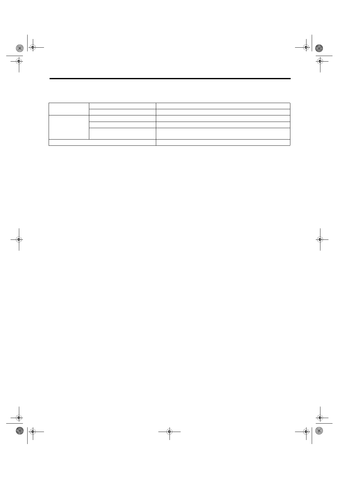
A: SPECIFICATION
Fuel tank
Capacity
64 L (16.9 US gal, 14.1 Imp gal)
Location
Under rear seat
Fuel pump
Type
Impeller
Shutoff discharge pressure
900 kPa (9.18 kg/cm
2
, 130.5 psi), or less
Discharge rate
175 L (46.2 US gal, 38.5 Imp gal)/h or more
[12 V at 300 kPa (3.06 kg/cm
2
, 43.5 psi)]
Fuel filter
In-tank type
FU(STI)-15
Throttle Body
FUEL INJECTION (FUEL SYSTEMS)
2. Throttle Body
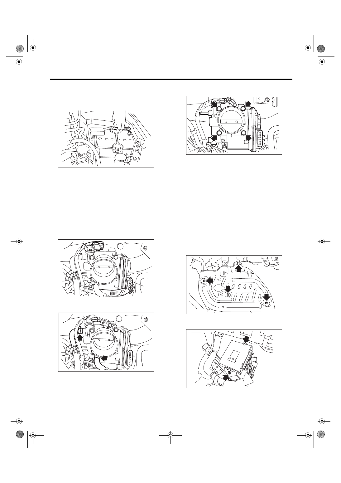
A: REMOVAL
1) Disconnect the ground cable from battery.
2) Lift up the vehicle.
3) Remove the under cover. <Ref. to EI-28, RE-
4) Drain approximately 3.0 L (3.2 US qt, 2.6 Imp qt)
of coolant. <Ref. to CO(STI)-13, DRAINING OF
ENGINE COOLANT, REPLACEMENT, Engine
5) Remove the intercooler. <Ref. to IN(STI)-12,
6) Disconnect the connector (A) from the throttle
position sensor, and the connector (B) from the
manifold pressure sensor.
7) Disconnect the engine coolant hose from throttle
body.
8) Remove the throttle body from the intake mani-
fold.
B: INSTALLATION
Install in the reverse order of removal.
NOTE:
Use a new gasket.
Tightening torque:
8 N·m (0.8 kgf-m, 5.9 ft-lb)
C: INSPECTION
1. THROTTLE SENSOR INSPECTION
(METHOD WITH CIRCUIT TESTER)
1) Remove the lower inner trim of passenger’s
side. <Ref. to EI-57, REMOVAL, Lower Inner
2) Turn over the floor mat of passenger’s seat.
3) Remove the protect cover.
4) Remove the nuts and bolts which hold the ECM
to the bracket.
5) Turn the ignition switch to ON. (engine OFF)
IN-00203
FU-05759
(B)
(A)
FU-05760
FU-05691
FU-03416
FU-03417
Нет комментариевНе стесняйтесь поделиться с нами вашим ценным мнением.
Текст