Subaru Impreza 3 / Impreza WRX / Impreza WRX STI. Service manual — part 672
LI-11
Combination Switch (Light)
LIGHTING SYSTEM
9. Combination Switch (Light)
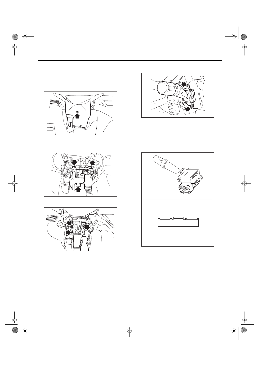
A: REMOVAL
1) Disconnect the ground cable from battery.
2) Remove the screws and remove the steering
column cover lower.
3) Remove the harness cover lock.
4) Remove the screws and detach the knee protec-
tor.
5) Remove the mounting screws of steering col-
umn cover upper.
6) Disconnect the connector from combination
switch.
7) Remove the screws which secure the switch,
then remove the combination switch.
B: INSTALLATION
Install each part in the reverse order of removal.
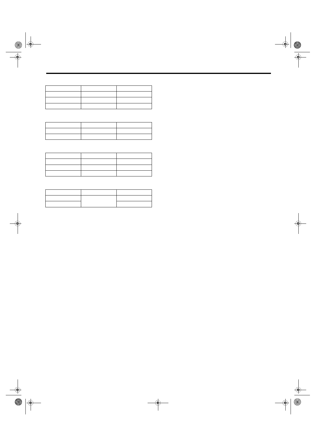
C: INSPECTION
1) Disconnect the combination switch connector.
2) Check the resistance between combination
switch terminals.
3) Replace the combination switch (light) if the in-
spection result of each switch is not within the stan-
dard value.
WW-00547
LI-01143
LI-01144
LI-00331
OFF
OFF
LI-00434
15 14 13 12 11 10
9
17
16
6 5 4
3
2
1
8
7
LI-12
Combination Switch (Light)
LIGHTING SYSTEM
1. LIGHTING SWITCH
2. DIMMER & PASSING SWITCH
3. TURN SIGNAL SWITCH
4. FRONT FOG LIGHT SWITCH
Switch position
Terminal No.
Standard value
OFF
—
1 MΩ or more
Tail
14 and 16
Less than 1 Ω
Head
13, 14 and 16
Less than 1 Ω
Switch position
Terminal No.
Standard value
Passing
7, 8 and 16
Less than 1 Ω
High beam
7 and 16
Less than 1 Ω
Switch position
Terminal No.
Standard value
Left
1 and 2
Less than 1 Ω
Neutral
—
1 MΩ or more
Right
3 and 2
Less than 1 Ω
Switch position
Terminal No.
Standard value
OFF
11 and 10
1 MΩ or more
ON
Less than 1 Ω
LI-13
Headlight Beam Leveler System
LIGHTING SYSTEM
10.Headlight Beam Leveler Sys-
tem
A: WIRING DIAGRAM
Refer to “Headlight Beam Leveler System” in WI
section. <Ref. to WI-93, WIRING DIAGRAM, Head-
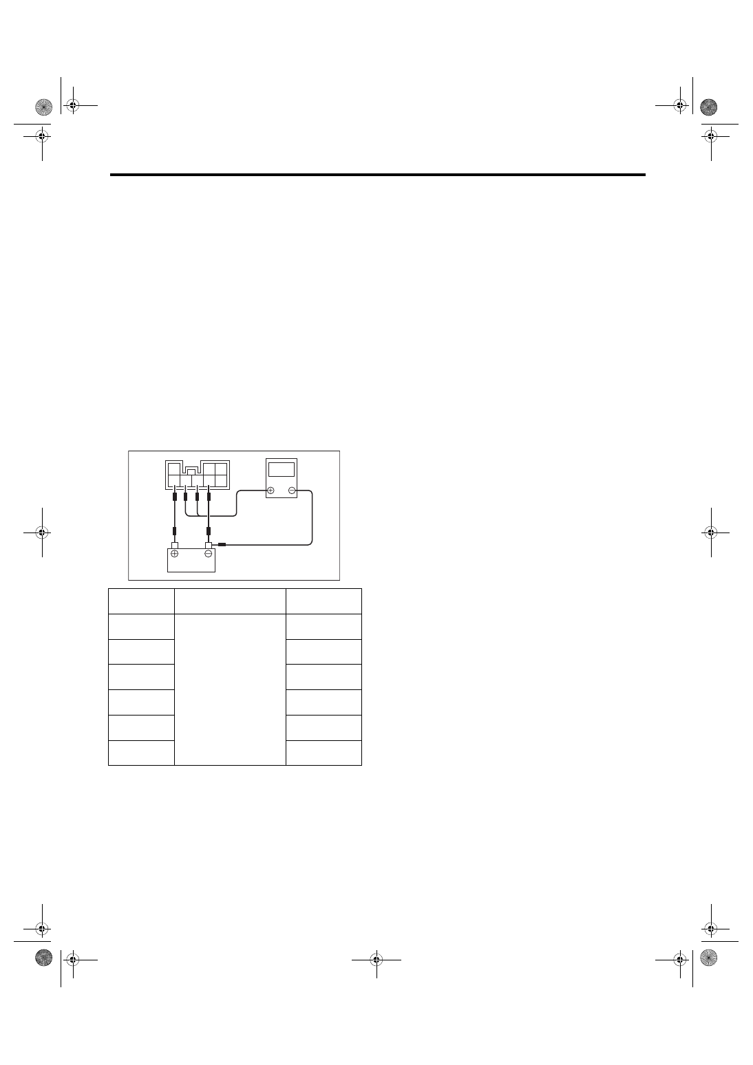
B: INSPECTION
1. HEADLIGHT BEAM LEVELER ACTUA-
TOR
1) Turn on the headlight beam.
2) Change the switch position in the order of 0 → 1
→ 2 → 3 → 4 → 5, and check that the headlight
beam position is lowered.
2. HEADLIGHT BEAM LEVELER SWITCH
1) Connect the circuit tester to the battery and
headlight beam leveler switch connector.
2) Check the voltage at each switch position.
3) Replace the headlight beam leveler switch if the
inspection result is not within the standard value.
Switch posi-
tion
Terminal No.
Standard value
0
6, 7 (+) and battery (–)
84 — 89% of
battery voltage
1
67 — 73% of
battery voltage
2
51 — 57% of
battery voltage
3
36 — 41% of
battery voltage
4
21 — 26% of
battery voltage
5
7 — 10% of bat-
tery voltage
LI-00270
v
3
2 1
8 7 6 5 4
LI-14
Combination Base Switch Assembly
LIGHTING SYSTEM
11.Combination Base Switch
Assembly
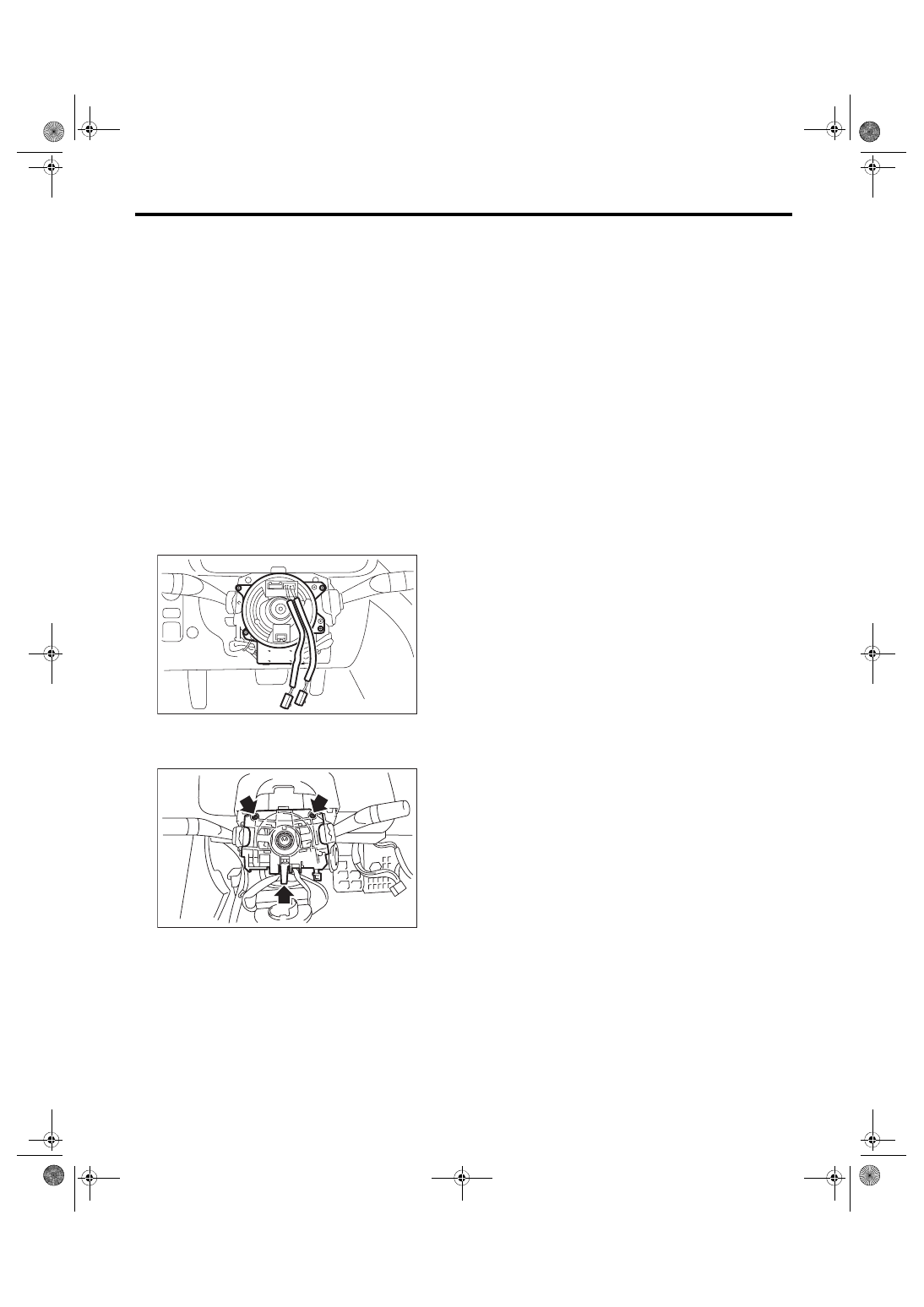
A: REMOVAL
1) Remove the driver’s airbag module. <Ref. to AB-
15, REMOVAL, Driver’s Airbag Module.>
WARNING:
Before handling the airbag module, refer to
“CAUTION” of “General Description” in the
“AB” section. <Ref. to AB-5, CAUTION, General
2) Remove the steering wheel. <Ref. to PS-13, RE-
3) Remove the combination switch.
• Combination switch (light): <Ref. to LI-11, RE-
MOVAL, Combination Switch (Light).>
• Combination switch (wiper): <Ref. to WW-7, RE-
MOVAL, Combination Switch (Wiper).>
4) Remove the screws, and then remove the roll
connector.
5) Remove the screws, disconnect the harness
connector and remove the combination base
switch assembly.
B: INSTALLATION
1) Before installing steering wheel, be sure to ad-
just the direction of roll connector with steering.
<Ref. to AB-27, ADJUSTMENT, Roll Connector.>
2) Install each part in the reverse order of removal.
C: INSPECTION
1. COMBINATION BASE SWITCH ASSEM-
BLY
Inspect the combination base switch assembly and
roll connector for cracks or deformation. If any
damage is found, replace with a new part.
AB-02604
LI-00271
Нет комментариевНе стесняйтесь поделиться с нами вашим ценным мнением.
Текст