Subaru Impreza 3 / Impreza WRX / Impreza WRX STI. Service manual — part 273
EN(H4DOTC)(diag)-316
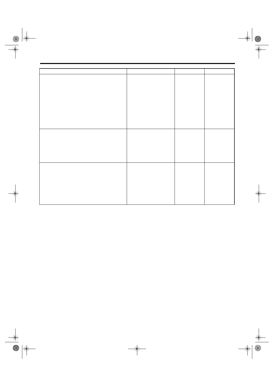
Diagnostic Procedure with Diagnostic Trouble Code (DTC)
ENGINE (DIAGNOSTICS)
Step
Check
Yes
No
1
CHECK HARNESS BETWEEN ECM AND
TUMBLE GENERATOR VALVE ASSEMBLY
RH CONNECTOR.
1) Turn the ignition switch to OFF.
2) Disconnect the connectors from the ECM
and tumble generator valve assembly RH.
3) Measure the resistance of harness between
ECM connector and tumble generator valve
assembly RH connector.
Connector & terminal
(B134) No. 25 — (E55) No. 5:
(B134) No. 26 — (E55) No. 4:
Is the resistance less than 1 Ω? Go to step
Repair the harness
and connector.
NOTE:
In this case, repair
the following item:
• Open circuit in
harness between
ECM
connector
and tumble gener-
ator valve assem-
bly RH connector
• Poor contact of
coupling connector
2
CHECK HARNESS BETWEEN ECM AND
TUMBLE GENERATOR VALVE ASSEMBLY
RH CONNECTOR.
Measure the resistance between ECM connec-
tor and chassis ground.
Connector & terminal
(B134) No. 25 — Chassis ground:
(B134) No. 26 — Chassis ground:
Is the resistance 1 MΩ or
more?
Repair the short
circuit to ground in
harness between
ECM connector
and tumble gener-
ator valve assem-
bly RH connector.
3
CHECK FOR POOR CONTACT.
Check for poor contact of tumble generator
valve assembly RH connector.
Is there poor contact of the tum-
ble generator valve assembly
RH connector?
Repair the poor
contact of tumble
generator valve
assembly RH con-
nector.
EN(H4DOTC)(diag)-317
Diagnostic Procedure with Diagnostic Trouble Code (DTC)
ENGINE (DIAGNOSTICS)
DV:DTC P2009 INTAKE MANIFOLD RUNNER CONTROL CIRCUIT LOW
(BANK 1)
DTC DETECTING CONDITION:
• Immediately at fault recognition
• GENERAL DESCRIPTION <Ref. to GD(H4DOTC)-222, DTC P2009 INTAKE MANIFOLD RUNNER CON-
TROL CIRCUIT LOW (BANK 1), Diagnostic Trouble Code (DTC) Detecting Criteria.>
CAUTION:
After servicing or replacing faulty parts, perform Clear Memory Mode <Ref. to EN(H4DOTC)(diag)-63,
OPERATION, Clear Memory Mode.>, and Inspection Mode <Ref. to EN(H4DOTC)(diag)-49, PROCE-
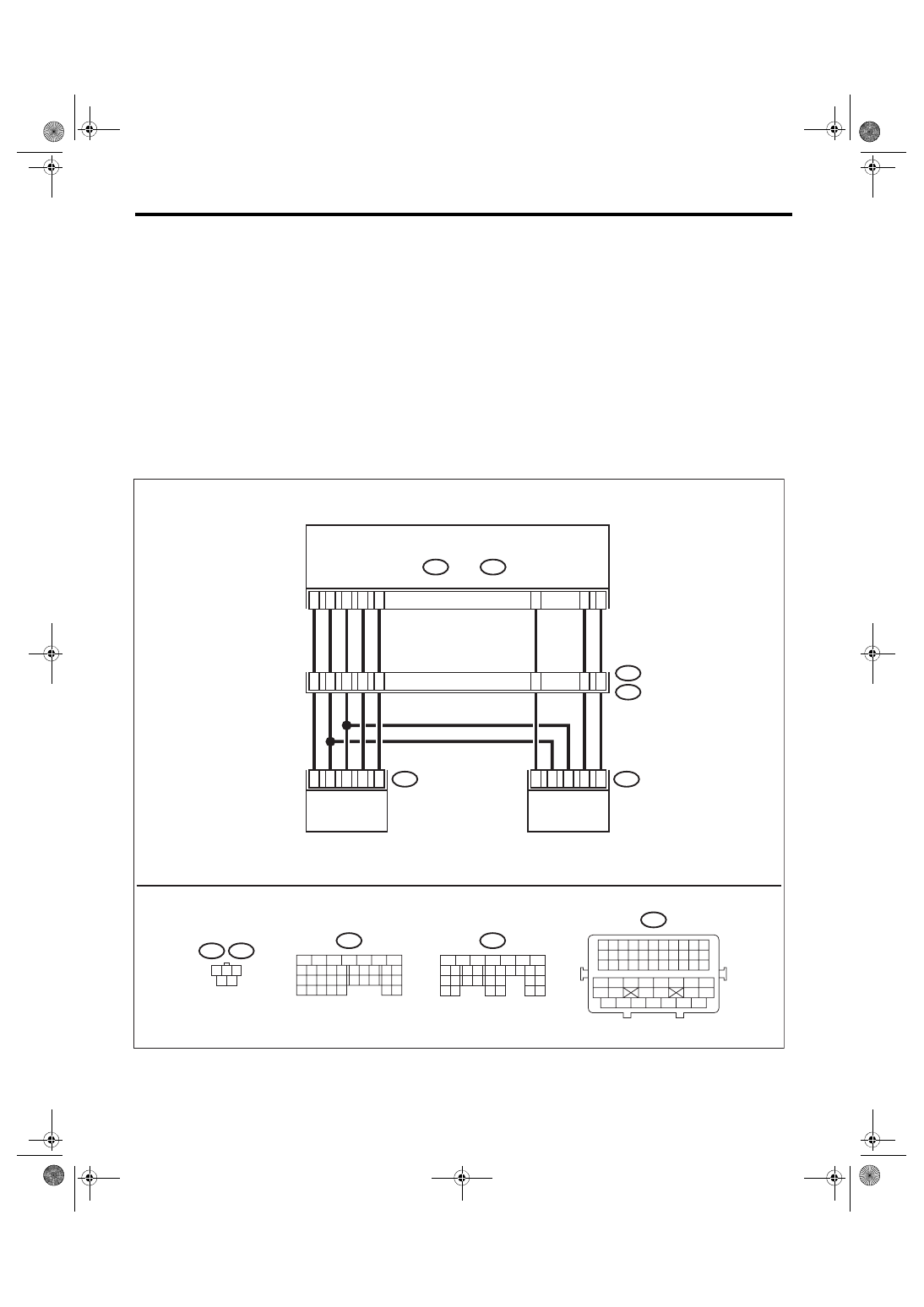
WIRING DIAGRAM:
• Engine electrical system, without SI-DRIVE <Ref. to WI-32, WITHOUT SI-DRIVE, WIRING DIAGRAM,
• Engine electrical system, with SI-DRIVE <Ref. to WI-48, WITH SI-DRIVE, WIRING DIAGRAM, Engine
ECM
E2
B21
A25
D11
A26
A23
A19
D10
A29
A24
1 2 3
4 5
E51
E55
B134
A:
B137
D:
8
16
19
29
2
8
27
6
30
4
2
1
3
5
E55
4
2
1
3
5
E51
5
6
7
8
2
1
9
4
3
10
22 23
11 12 13 14 15
24 25
26
16 17
18 19 20 21
27
28 29
30 31
B137
D:
5
6
7
8
2
1
9
4
3
10
24
22 23
25
11 12 13 14 15
26 27
28
16 17
18 19 20 21
33 34
29
32
30 31
B134
A:
B21
1 2 3 4 5 6 7 8 9 10 11
12 13 14 15 16 17 18 19 20 21 22
23 24 25 26 27 28 29 30 31 32 33
34 35
42 43
36 37 38 39
48 49 50 51 52 53 54
40 41
44 45
46 47
EN-09253
TUMBLE GENERATOR
VALVE ACTUATOR LH
TUMBLE GENERATOR
VALVE ACTUATOR RH
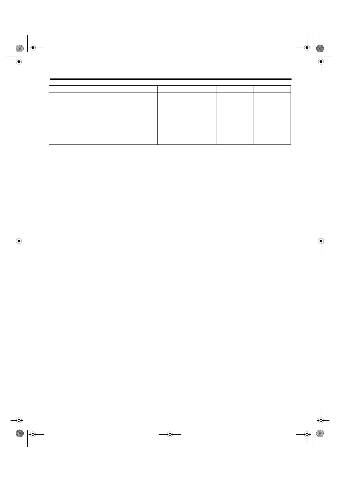
EN(H4DOTC)(diag)-318
Diagnostic Procedure with Diagnostic Trouble Code (DTC)
ENGINE (DIAGNOSTICS)
Step
Check
Yes
No
1
CHECK HARNESS BETWEEN ECM AND
TUMBLE GENERATOR VALVE ASSEMBLY
RH CONNECTOR.
1) Turn the ignition switch to OFF.
2) Disconnect the connector from ECM.
3) Measure the voltage between ECM connec-
tor and chassis ground.
Connector & terminal
(B134) No. 25 (+) — Chassis ground (–):
(B134) No. 26 (+) — Chassis ground (–):
Is the voltage 5 V or more?
Repair the short
circuit to power in
harness between
ECM connector
and tumble gener-
ator valve assem-
bly RH connector.

EN(H4DOTC)(diag)-319
Diagnostic Procedure with Diagnostic Trouble Code (DTC)
ENGINE (DIAGNOSTICS)
DW:DTC P2011 INTAKE MANIFOLD RUNNER CONTROL CIRCUIT / OPEN
(BANK 2)
DTC DETECTING CONDITION:
• Immediately at fault recognition
• GENERAL DESCRIPTION <Ref. to GD(H4DOTC)-223, DTC P2011 INTAKE MANIFOLD RUNNER CON-
TROL CIRCUIT / OPEN (BANK 2), Diagnostic Trouble Code (DTC) Detecting Criteria.>
CAUTION:
After servicing or replacing faulty parts, perform Clear Memory Mode <Ref. to EN(H4DOTC)(diag)-63,
OPERATION, Clear Memory Mode.>, and Inspection Mode <Ref. to EN(H4DOTC)(diag)-49, PROCE-
WIRING DIAGRAM:
• Engine electrical system, without SI-DRIVE <Ref. to WI-32, WITHOUT SI-DRIVE, WIRING DIAGRAM,
• Engine electrical system, with SI-DRIVE <Ref. to WI-48, WITH SI-DRIVE, WIRING DIAGRAM, Engine
ECM
E2
B21
A25
D11
A26
A23
A19
D10
A29
A24
1 2 3
4 5
E51
E55
B134
A:
B137
D:
8
16
19
29
2
8
27
6
30
4
2
1
3
5
E55
4
2
1
3
5
E51
5
6
7
8
2
1
9
4
3
10
22 23
11 12 13 14 15
24 25
26
16 17
18 19 20 21
27
28 29
30 31
B137
D:
5
6
7
8
2
1
9
4
3
10
24
22 23
25
11 12 13 14 15
26 27
28
16 17
18 19 20 21
33 34
29
32
30 31
B134
A:
B21
1 2 3 4 5 6 7 8 9 10 11
12 13 14 15 16 17 18 19 20 21 22
23 24 25 26 27 28 29 30 31 32 33
34 35
42 43
36 37 38 39
48 49 50 51 52 53 54
40 41
44 45
46 47
EN-09253
TUMBLE GENERATOR
VALVE ACTUATOR LH
TUMBLE GENERATOR
VALVE ACTUATOR RH
Нет комментариевНе стесняйтесь поделиться с нами вашим ценным мнением.
Текст