Subaru Impreza 3 / Impreza WRX / Impreza WRX STI. Service manual — part 259
EN(H4DOTC)(diag)-260
Diagnostic Procedure with Diagnostic Trouble Code (DTC)
ENGINE (DIAGNOSTICS)
Step
Check
Yes
No
1
CHECK CURRENT DATA.
1) Turn the ignition switch to ON.
2) Read the value of «Atmosphere Pressure»
using the Subaru Select Monitor or a general
scan tool.
NOTE:
• Subaru Select Monitor
For detailed operation procedures, refer to
“READ CURRENT DATA FOR ENGINE”. <Ref.
to EN(H4DOTC)(diag)-40, Subaru Select Moni-
tor.>
• General scan tool
For detailed operation procedures, refer to the
general scan tool operation manual.
Is the value in «Atmosphere
Pressure» 125 kPa (938
mmHg, 36.9 inHg) or more?
Even if DTC is
detected, the cir-
cuit has returned to
a normal condition
at this time. Repro-
duce the failure,
and then perform
the diagnosis
again.
NOTE:
In this case, tem-
porary poor con-
tact of connector,
temporary open or
short circuit of har-
ness may be the
cause.
2
CHECK HARNESS BETWEEN ECM AND
LEAK CHECK VALVE ASSEMBLY CONNEC-
TOR.
1) Turn the ignition switch to OFF.
2) Disconnect the connector from ECM and
the leak check valve assembly.
3) Measure the resistance of harness between
ECM connector and the leak check valve
assembly connector.
Connector & terminal
(B136) No. 21 — (R400) No. 7:
(B135) No. 30 — (R400) No. 8:
Is the resistance less than 1 Ω? Go to step
Repair the harness
and connector.
NOTE:
In this case, repair
the following item:
• Open circuit in
harness between
ECM
connector
and the leak check
valve
assembly
connector
• Poor contact of
coupling connector
• Poor contact of
joint connector
3
CHECK FOR POOR CONTACT.
Check for poor contact of ECM and the leak
check valve assembly connector.
Is there poor contact in ECM
and the leak check valve
assembly connector?
Repair the poor
contact of ECM
and the leak check
valve assembly
connector.
4
CHECK LEAK CHECK VALVE ASSEMBLY.
Check the pressure sensor of the leak check
valve assembly. <Ref. to EC(STI)-21, CHECK
PRESSURE SENSOR, INSPECTION, Leak
Check Valve Assembly.> <Ref. to EC(w/o STI)-
22, CHECK PRESSURE SENSOR, INSPEC-
TION, Leak Check Valve Assembly.>
Is the pressure sensor of the
leak check valve assembly
OK?
Repair the short
circuit to power in
harness between
ECM connector
and leak check
valve assembly
connector.
EN(H4DOTC)(diag)-261
Diagnostic Procedure with Diagnostic Trouble Code (DTC)
ENGINE (DIAGNOSTICS)
CK:DTC P0455 EVAPORATIVE EMISSION SYSTEM LEAK DETECTED (LARGE
LEAK)
DTC DETECTING CONDITION:
• Detected when two consecutive driving cycles with fault occur.
• GENERAL DESCRIPTION <Ref. to GD(H4DOTC)-161, DTC P0455 EVAPORATIVE EMISSION SYS-
TEM LEAK DETECTED (LARGE LEAK), Diagnostic Trouble Code (DTC) Detecting Criteria.>
TROUBLE SYMPTOM:
• Fuel odor
• There is a hole of more than 1.0 mm (0.04 in) dia. in evaporation system or fuel tank.
• Fuel filler cap loose or lost
CAUTION:
After servicing or replacing faulty parts, perform Clear Memory Mode <Ref. to EN(H4DOTC)(diag)-63,
OPERATION, Clear Memory Mode.>, and Inspection Mode <Ref. to EN(H4DOTC)(diag)-49, PROCE-
Step
Check
Yes
No
1
CHECK FUEL FILLER CAP.
1) Turn the ignition switch to OFF.
2) Check the fuel filler cap.
NOTE:
The DTC is stored in memory if fuel filler cap is
or was loose or if the cap chain has caught while
tightening.
Is the fuel filler cap tightened
securely?
Tighten fuel filler
cap securely.
2
CHECK FUEL FILLER CAP.
Is the fuel filler cap genuine?
Replace with a
genuine fuel filler
cap.
3
CHECK FUEL FILLER PIPE GASKET.
Is there any damage to the seal
between fuel filler cap and fuel
filler pipe?
4
CHECK PURGE CONTROL SOLENOID
VALVE.
Check air-tightness of the purge control sole-
noid valve. <Ref. to EC(STI)-12, INSPECTION,
Purge Control Solenoid Valve.> <Ref. to EC(w/
o STI)-13, INSPECTION, Purge Control Sole-
noid Valve.>
Is the purge control solenoid
valve OK?
5
CHECK EVAPORATIVE EMISSION CON-
TROL SYSTEM LINE.
Are there holes on the evapora-
tion line?
EN(H4DOTC)(diag)-262
Diagnostic Procedure with Diagnostic Trouble Code (DTC)
ENGINE (DIAGNOSTICS)
CL:DTC P0456 EVAPORATIVE EMISSION CONTROL SYSTEM LEAK DETECT-
ED (VERY SMALL LEAK)
NOTE:
For the diagnostic procedure, refer to DTC P0455. <Ref. to EN(H4DOTC)(diag)-261, DTC P0455 EVAPO-
RATIVE EMISSION SYSTEM LEAK DETECTED (LARGE LEAK), Diagnostic Procedure with Diagnostic
6
CHECK CANISTER.
Are there holes on the canis-
ter?
Replace the canis-
ter. <Ref. to
EC(STI)-7, Canis-
ter.> <Ref. to
EC(w/o STI)-7,
Canister.>
7
CHECK LEAK CHECK VALVE ASSEMBLY. Are there damage or holes on
the leak check valve assembly?
8
CHECK FUEL TANK.
Remove the fuel tank. <Ref. to FU(STI)-70, Fuel
Tank.> <Ref. to FU(w/o STI)-68, Fuel Tank.>
Are there damage or holes on
the fuel tank?
9
CHECK ANY OTHER MECHANICAL TROU-
BLE IN EVAPORATIVE EMISSION CON-
TROL SYSTEM.
Are there holes, cracks, clog-
ging, or disconnection, miscon-
nection of hoses or pipes in
evaporative emission control
system?
Repair or replace
the hoses or pipes.
Repair the poor
contact of ECM
connector.
Step
Check
Yes
No
EN(H4DOTC)(diag)-263
Diagnostic Procedure with Diagnostic Trouble Code (DTC)
ENGINE (DIAGNOSTICS)
CM:DTC P0458 EVAPORATIVE EMISSION SYSTEM PURGE CONTROL VALVE
CIRCUIT LOW
DTC DETECTING CONDITION:
• Detected when 2 consecutive driving cycles with fault occur.
• GENERAL DESCRIPTION <Ref. to GD(H4DOTC)-168, DTC P0458 EVAPORATIVE EMISSION SYS-
TEM PURGE CONTROL VALVE CIRCUIT LOW, Diagnostic Trouble Code (DTC) Detecting Criteria.>
TROUBLE SYMPTOM:
Improper idling
CAUTION:
After servicing or replacing faulty parts, perform Clear Memory Mode <Ref. to EN(H4DOTC)(diag)-63,
OPERATION, Clear Memory Mode.>, and Inspection Mode <Ref. to EN(H4DOTC)(diag)-49, PROCE-
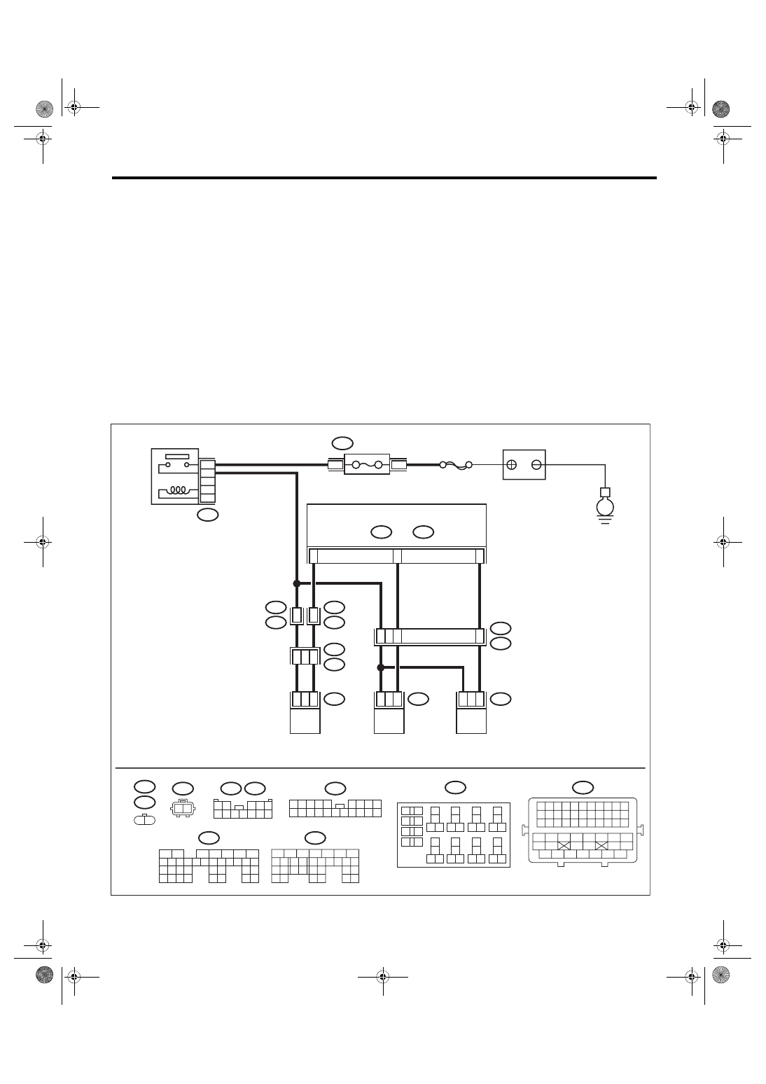
WIRING DIAGRAM:
• Engine electrical system, without SI-DRIVE <Ref. to WI-32, WITHOUT SI-DRIVE, WIRING DIAGRAM,
• Engine electrical system, with SI-DRIVE <Ref. to WI-48, WITH SI-DRIVE, WIRING DIAGRAM, Engine
ECM
5
6
7
8
2
1
9
4
3
10
24
22 23
25
11 12 13 14 15
26 27
28
16 17 18 19
20 21
29 30 31
32 33
34 35
B135
B:
5
6
7
8
2
1
9
4
3
10
22 23
11 12 13 14 15
24 25
26
16 17
18 19 20 21
27
28 29
30 31
B137
D:
B21
1 2 3 4 5 6 7 8 9 10 11
12 13 14 15 16 17 18 19 20 21 22
23 24 25 26 27 28 29 30 31 32 33
34 35
42 43
36 37 38 39
48 49 50 51 52 53 54
40 41
44 45
46 47
E52
E4
1 2
B3
D15
D6
E2
B21
44
11
4
8
E4
2
1
E52
2
1
R68
2
1
B135
B:
R57
R15
10
11
R1
B97
R2
B98
7
10
R68
1 2
B220
13
14
15 16
17
27
24
25
26
20
21
22
23
29
30
31
28
32 35
33
34
37
38
39
36
40
8
9
10
11 12
1
2
5
3
4
7
6
19
18
R57
B97
1 2
3 4 5
6 7 8 9 10 11 12
EN-09251
B98
2 3 4 5
6 7 8 9
11 12 13 14
17 18 19 20
1
10
15 16
B220
24
23
22
21
B220
4
3
B137
D:
SBF-7
E
FUSE
(RELAY BLOCK)
MAIN RELAY
BATTERY
PRESSURE CONTROL
SOLENOID VALVE ASSY
PURGE CONTROL
SOLENOID VALVE 2
PURGE CONTROL
SOLENOID VALVE 1
Нет комментариевНе стесняйтесь поделиться с нами вашим ценным мнением.
Текст