Subaru Impreza 3 / Impreza WRX / Impreza WRX STI. Service manual — part 775
LAN(diag)-9
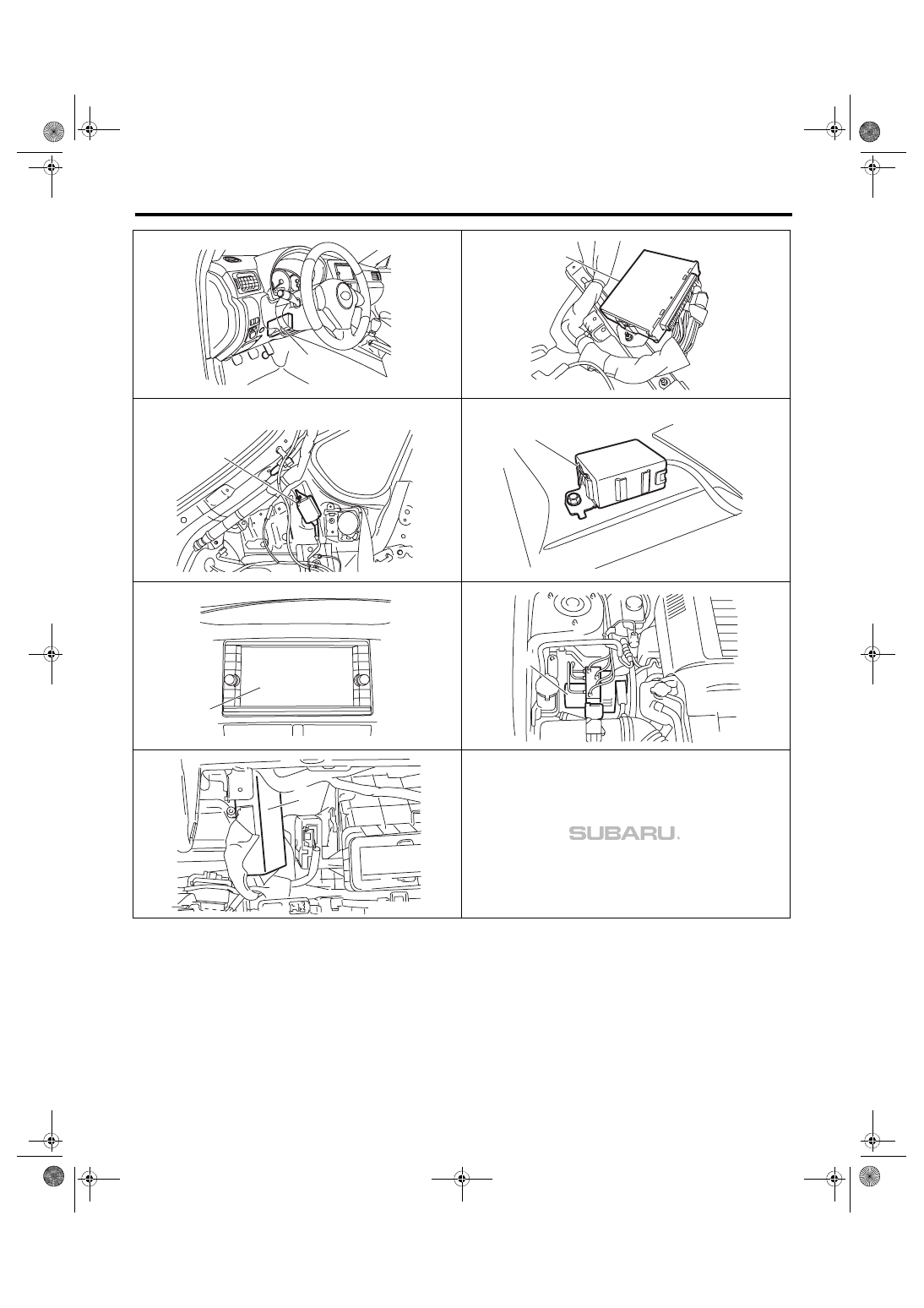
Electrical Component Location
LAN SYSTEM (DIAGNOSTICS)
5 door model
4 door model
(1)
LAN00339
LAN00425
(2)
LAN00905
(5)
LAN00909
(5)
LAN00299
(7)
LAN00008
(11)
(8)
LAN00350
LAN(diag)-10
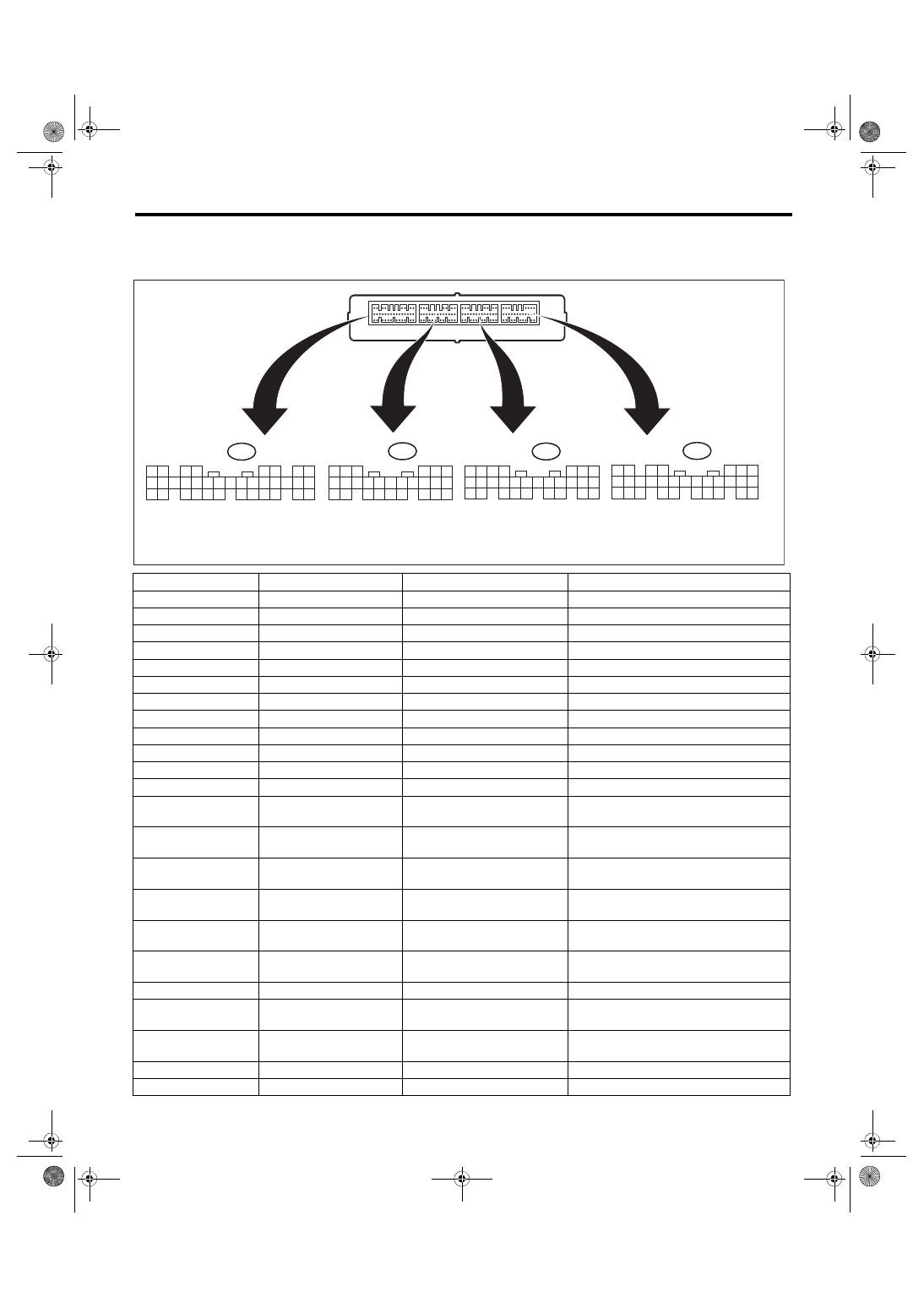
Control Module I/O Signal
LAN SYSTEM (DIAGNOSTICS)
5. Control Module I/O Signal
A: ELECTRICAL SPECIFICATION
Contents
Terminal No.
Standard
Measuring condition
BAT (control)
B6 ←→ chassis ground
9 — 16 V
Always
BAT (backup)
C2 ←→ chassis ground
9 — 16 V
Always
BAT (door lock)
A34 ←→ chassis ground
9 — 16 V
Always
ACC (rear wiper)
D21 ←→ chassis ground
Less than 1.5 V → 9 — 16 V
ACC OFF → ACC ON
Ground
A28 ←→ chassis ground
Less than 1.5 V
Always
Ground
B17 ←→ chassis ground
Less than 1.5 V
Always
Ground
C20 ←→ chassis ground
Less than 1.5 V
Always
Ground
D27 ←→ chassis ground
Less than 1.5 V
Always
Key warning switch
D2 ←→ chassis ground
Less than 1.5 V → 9 — 16 V
With key removed → inserted
ACC
B7 ←→ chassis ground
Less than 1.5 V → 9 — 16 V
ACC OFF → ACC ON
IGN
B1 ←→ chassis ground
Less than 1.5 V → 9 — 16 V
IGN OFF → IGN ON
Stop light switch
B2 ←→ chassis ground
Less than 1.5 V → 8 V or more
With brake pedal released → depressed
Door switch, driver’s
seat
A19 ←→ chassis ground
8 V or more → less than 1.5 V
With driver’s door closed → opened
Door switch, passen-
ger’s seat
A32 ←→ chassis ground
8 V or more → less than 1.5 V
With passenger’s door closed → opened
Door switch, rear RH
seat
A6 ←→ chassis ground
8 V or more → less than 1.5 V
With rear RH seat door closed → opened
Door switch, rear LH
seat
A20 ←→ chassis ground
8 V or more → less than 1.5 V
With rear LH seat door closed → opened
Door switch, trunk/rear
gate
A33 ←→ chassis ground
8 V or more → less than 1.5 V
With trunk or rear gate closed → opened
Rear gate opener but-
ton
C24 ←→ chassis ground
8 V or more → less than 1.5 V
Switch OFF → ON
Manual switch (LOCK)
A15 ←→ chassis ground
8 V or more → less than 1.5 V
Switch OFF → ON
Manual switch
(UNLOCK)
A29 ←→ chassis ground
8 V or more → less than 1.5 V
Switch OFF → ON
Delivery (test) mode
connector
A17 ←→ chassis ground
8 V or more → less than 1.5 V
When delivery (test) mode connector is
connected
Front wiper input RTN
C5 ←→ chassis ground
8 V or more → less than 1.5 V
When front wiper is reversed
Rear wiper switch ON
C18 ←→ chassis ground
8 V or more → less than 1.5 V
Switch OFF → ON
SIDE
A: i84
1
2
3
4
5
6
7
8
9
10
11
12
14
15
16
17
18
19
20
21
22
23
24
25
26
27
28
29
30
31
32
33
34
35
13
B281
C:
B280
B:
B279
D:
1
2
3
4
5
6
7
8
9
10
11
12
14
15
16
17
18
19
20
21
22
23
24
25
26
13
1
2
3
4
5
6
7
8
9
10
11
12
14
15
16
17
18
19
20
21
22
23
24
25
26
27
28
13
1
2
3
4
5
6
7
8
9
10
11
12
14
15
16
17
18
19
20
21
22
23
24
25
26
27
28
29
30
13
LAN00314
SIDE
SIDE
SIDE
LAN(diag)-11
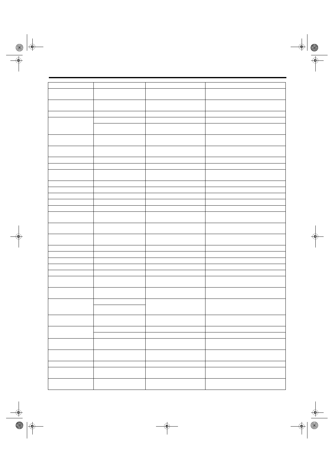
Control Module I/O Signal
LAN SYSTEM (DIAGNOSTICS)
Rear wiper switch
(INT)
C27 ←→ chassis ground
8 V or more → less than 1.5 V
Switch OFF → ON
Rear wiper switch
washer
C28 ←→ chassis ground
8 V or more → less than 1.5 V
Switch OFF → ON
Lighting I switch
B11 ←→ chassis ground
8 V or more → less than 1.5 V
Switch OFF → ON
Lighting II switch
C8 ←→ chassis ground
8 V or more → less than 1.5 V
Switch OFF → ON
D6 ←→ chassis ground
8 V or more → less than 1.5 V
Key warning switch ON and lighting switch
OFF → ON
Dimmer switch, Hi
beam
B12 ←→ chassis ground
8 V or more → less than 1.5 V
Switch OFF → ON
Dimmer switch, pass-
ing
B22 ←→ chassis ground
8 V or more → less than 1.5 V
Switch OFF → ON
Front fog light switch
B24 ←→ chassis ground
8 V or more → less than 1.5 V
Switch OFF → ON
MT reverse switch
B18 ←→ chassis ground
Less than 1.5 V → 8 V or more
Other than reverse → reverse
Parking brake switch
C15 ←→ chassis ground
8 V or more → less than 1.5 V
With parking brake not operated → oper-
ated
Bright switch
A14 ←→ chassis ground
Less than 1.5 V → 8 V or more
Switch OFF → ON
Illumination (Vi1)
A12 ←→ chassis ground
Approx. 5 V
Always
Illumination (Vi2)
A3 ←→ chassis ground
0.5 V — 5.0 V
Always
Illumination (Vi3)
A26 ←→ chassis ground
Less than 1.5 V
Always
Fuel level sensor
C7 ←→ chassis ground
Approx. 2 — 96 Ω
Ignition ON
Wiper deicer & rear
defogger switch
A16 ←→ chassis ground
8 V or more → less than 1.5 V
Switch OFF → ON
Seat belt switch
(driver’s seat)
C16 ←→ chassis ground
Less than 1.5 V → 8 V or more
With seat belt unbuckled → buckled
Seat belt switch (pas-
senger’s seat)
C26 ←→ chassis ground
Less than 1.5 V → 8 V or more
With seat belt unbuckled → buckled
Impact sensor
B8 ←→ chassis ground
Less than 1.5 V → 8 V or more
When a shock is applied
Rear wiper output ON
D9 ←→ chassis ground
Less than 1 V → 9 V or more
When rear wiper operates
Rear wiper output RTN
D8 ←→ chassis ground
Less than 1 V → 9 V or more
When rear wiper reversed
Door lock output
A7 ←→ A8
Less than 1 V → 9 V or more
During lock output
Door unlock output
A8 ←→ A7
Less than 1 V → 9 V or more
While unlock output
Driver’s side door
unlock output
A23 ←→ A7
Less than 1 V → 9 V or more
While unlock output
Trunk/rear gate
UNLOCK output
A22 ←→ chassis ground
Less than 1 V → 9 V or more
4 door: While trunk UNLOCK output
5 door: While rear gate UNLOCK output
Lighting power supply
C1 ←→ chassis ground
Less than 1 V → 9 V or more
“With back-up fuse inserted, ACC ON or
IGN ON” or
“When key warning switch is ON”
D1 ←→ chassis ground
Clearance light relay
output
D19 ←→ chassis ground
9 V or more → less than 1 V
Small light ON
Lo beam relay output
C3 ←→ chassis ground
9 V or more → less than 1 V
Headlight switch ON
D7 ←→ chassis ground
9 V or more → less than 1 V
Headlight switch ON
Hi beam relay output
D20 ←→ chassis ground
9 V or more → less than 1 V
“Headlight switch ON and Hi beam ON” or
“Passing switch ON”
Front fog light relay
output
D17 ←→ chassis ground
9 V or more → less than 1 V
Headlight switch ON, and front fog light
switch ON
DRL cancel output
D18 ←→ chassis ground
9 V or more → less than 1 V
When Hi beam 100 % illuminates
Room light output
D5
Pulse control
Illumination is adjusted through PWM con-
trol
Key ring illumination
output
C23
Pulse control
Illumination is adjusted through PWM con-
trol
Contents
Terminal No.
Standard
Measuring condition
LAN(diag)-12
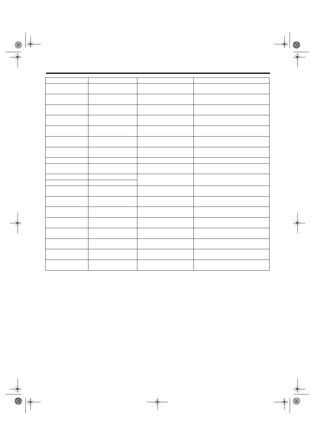
Control Module I/O Signal
LAN SYSTEM (DIAGNOSTICS)
B: WIRING DIAGRAM
<Ref. to WI-171, WIRING DIAGRAM, CAN Communication System.>
Illumination output
A2
Pulse control
Illumination is adjusted through PWM con-
trol
Map light output
(model with sunroof)
D4 ←→ chassis ground
Pulse control
Illumination is adjusted through PWM con-
trol
Rear defogger relay
output
D16 ←→ chassis ground
9 V or more → less than 1 V
While rear defogger output
Wiper deicer relay out-
put
D15 ←→ chassis ground
9 V or more → less than 1 V
While wiper deicer output
Seat belt warning light
(passenger’s seat)
A25 ←→ chassis ground
9 V or more → less than 1 V
Indicator go off → illuminate
Buzzer sound output
D24 ←→ chassis ground
Less than 1 V → 9 V or more
Door lock → unlock with keyless entry
system
Turn & hazard output
C22 ←→ chassis ground
9 V or more → less than 1 V
Door lock or unlock with keyless entry sys-
tem
Horn relay output
D29 ←→ chassis ground
9 V or more → less than 1 V
During security alarm operation
Security indicator out-
put
A10 ←→ chassis ground
9 V or more → less than 3 V
While indicator in combination meter
blinks
Immobilizer antenna 1
B26 ←→ B25
–30 — +30 V
While key secret code is verified
Immobilizer antenna 2
B25 ←→ B26
Immobilizer
communication_1
B4
Can not be measured because
of digital communication
Serial communication line
Immobilizer
communication_2
B15
Can not be measured because
of digital communication
Serial communication line
Keyless entry module
communication
A24
Can not be measured because
of digital communication
Serial communication line
SSM communication
(K line)
B20
Can not be measured because
of digital communication
Serial communication line
Body system CAN_Hi
A1 ←→ chassis ground
Can not be measured because
of digital communication
Serial communication line
Body system CAN_Lo
A9 ←→ chassis ground
Can not be measured because
of digital communication
Serial communication line
Driving system
CAN_Hi
B3 ←→ chassis ground
Can not be measured because
of digital communication
Serial communication line
Driving system
CAN_Lo
B9 ←→ chassis ground
Can not be measured because
of digital communication
Serial communication line
Contents
Terminal No.
Standard
Measuring condition
Нет комментариевНе стесняйтесь поделиться с нами вашим ценным мнением.
Текст